Note: Skip to the Tile section below if you’re only interested in seeing how virtual textures work.
UPDATE: This technique does not work. I’m leaving the article up because it provides information on how to use UDIM. But it does NOT fix the tile overlap issue.
I really wanted to continue on the resource management game. And it will get completed eventually, but the animations required were making it impossible to make any real progress. I’ve found that these items take most of my time.
- UI (I’ve always been slow at UI)
- Animations
- Asset creation and fixing
That last part… about fixing… is tweaking details, textures, render settings, etc. You can spend days, weeks and months just messing around with things before you realize all your time is gone.
So I have every intention of finishing the robot resource management game. But I need to get something out much faster. I decided on a Tower Defense game. Not everyone likes them, but there doesn’t seem to be that many on Steam that I’d play.
I gave myself two weeks to come up with a prototype and see how far I’d get. After the first week, I’d only spent times on a tile editor. I had 8×8 grid and an Unreal Editor panel where I could specify what tiles I wanted in the grid. I also needed blueprints to create the tileset. It was a lot of work. I then got sick with a cold. When the second week resumed, I made a Sniper turret, had a basic UI, one enemy and a weird way to make a hole for the turret to come out. In other words, in two weeks, I had a working concept. I was already way ahead of where I was with the other game.
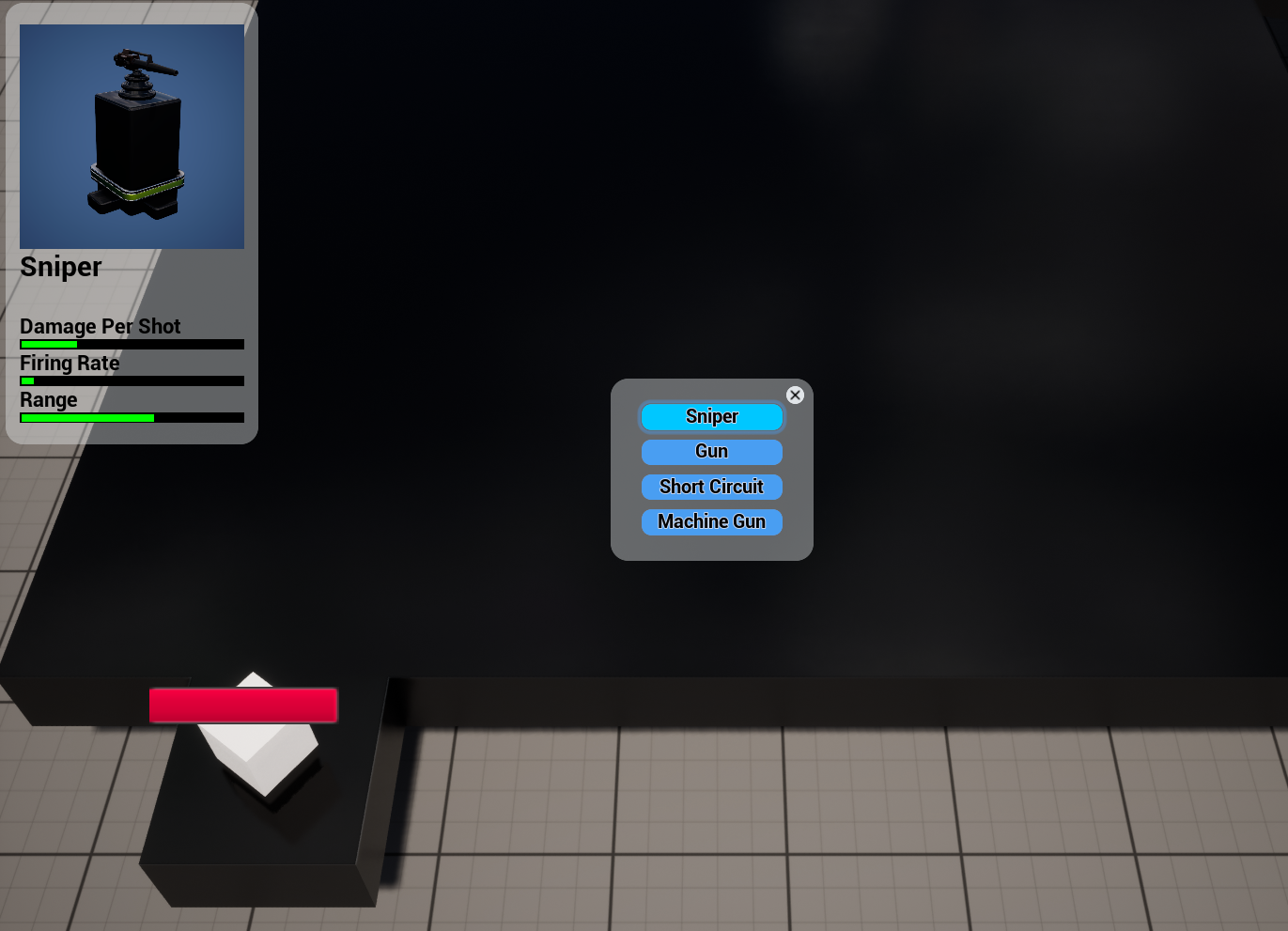
Basic tower selection menu. The stats panel renders the turrets in real time. They are not static images. I may animate them later. And I even have a health bar over my placeholder enemy. Don’t worry, the health bar is a normal size when you’re not zoomed in that close. It also supports shielded enemies. Some turrets are better against shields. The turret bases are placeholders as well, but we’ll see.
Already, this is kind of playable for a prototype (everything can and will change in final release). I just need more enemies. Sniper and Gun work. You can hover over a turret and see its range with a transparent overlay circle. Machine gun has an extra overheating stat that I need to hook up and get some special effects for. Oh yeah, the turrets track an enemy and when it is in line, it shoots and keeps tracking for a bit afterwards in case it shoots again. There is recoil and there is special effects for a bit of fire and smoke after each shot. But that’s for another day.
Tile Section
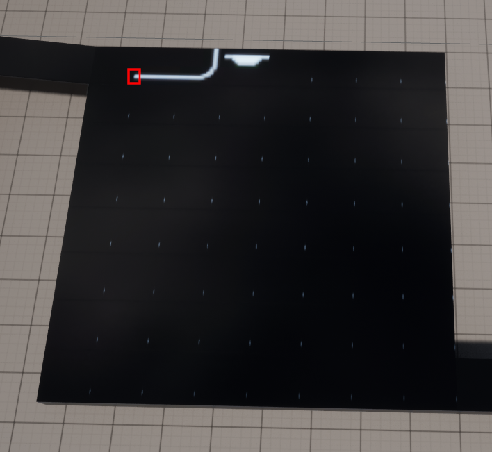
The large slab in the image above is an 8×8 tiled area. I wanted to be able to select from a list of tiles. I wanted to start with allowing at least 16 tiles. But with 6 attributes each (color, specular, metallic, roughness, normal and bump), that makes for 96 texture samples. That’s ridiculous. So I tried to put them all together into a single 4K x 4K texture. I wrote a blueprint to do this for me. And what you get is not very good. Here is an example of the first 4 tiles and the rest being black.
First, never mind that the texture is using the wrong resolution here. I had to force it to display lower resolutions since I had to undo many of the fixes I have implemented. It shows up the same even with the correct resolution.
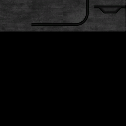
How does this work? There is a source (licensed) tileset with all the source tile textures. Here it is. Only the first four tiles are populated for now. This is the roughness texture.
There is another tiny 8×8 lookup texture that indicates which tile to use from the tileset above. So we can populate the 8×8 grid in any way we want.
I made the first four tiles in the 8×8 grid use the same tiles just so the reader can see the adjacent layout of the tiles.
Finally, what are those repeated dots in the screenshot above? Well, there’s a bump map on white lines to make them appear as if they stand out. The way bump map is implemented in UE is that it samples neighbouring texture pixels. So for those pixels on the edge of a tile, it will sample pixels from the neighbouring tile and you get this effect. The section inside the red square is what is getting duplicated. Actually, it’s from the tileset texture above. Keeping them in the same order makes it easier to visualize how the engine would sample from a neighbouring tile.
This effect of using neighbouring texture pixels happens even without bump mapping (bilinear will use 4 adjacent pixels for example) . It’s just that bump mapping makes it worse.
Possible Fixes
My first attempt at fixing this was to use a technique I had used before with megatexturing. That is to add an 8 pixel border around each tile in the source tileset. This way, it will never sample the adjacent tile. Well, this works fine for the first four LODs, then the artifacts come back.
What is a LOD?
A LOD is a Level Of Detail. For textures, it’s usually called a MIP or mipmap. It is a lower resolution texture created from the original. The first level is usually half the width and height. The second level is a quarter the width and height. And so one. So as you zoom out, you will use coarser texture to get better renders. If you use the highest resolution, you will skip many pixels in the texture and it will look grainy.
So using the above technique, Unreal Engine does its own MIP creation and you will have an extra border for 4 levels. After that, you’ll be sampling adjacent tiles again. You can clamp the LODs from 0 to 3. And this will work if you specify in UE to load all LODs. If you don’t it won’t clamp until the correct LOD gets loaded in memory. So you’ll see artifacts until you zoom in at which point it will start to render correctly. It’ll still be grainy if you have more colourful tiles than I do here.
To completely fix it, you need to keep at least a 4 pixels border on each LOD. That would mean a 128 x 128 tile would contain 120×120 pixels of actual data. Never mind the blueprints to scale to this area and producing these textures. It’s a pain. The next level would be 64×64, but only 56×56 will contain actual data. That’s not even a multiple of two when it comes to actual data. So you can get shimmering effects just going from one LOD to another.
Virtual Textures
What are virtual textures? To explain this, we need to explain what happens to a normal texture. Normally, when you texture a cube for example, the entire cube (or surface) will sample each pixel according to its distance from the camera. So if it samples from LOD0, ALL of LOD0 must be read into GPU memory. If an object is slanted, it could use several texture LODs, all of which need to be loaded into memory at the same time even if most of it is unused. What virtual textures does is split up your textures into tiles and only loads the tiles in each LOD that it needs. In this way, if a player never zooms in close to an object, it will never be loaded. But even if the player does zoom in, it only loads those tiles the user sees.
Internally, Unreal Engine will do much the same things that were explained in the previous section. You need to specify the tile size and you need to specify a border size. That border is used for a similar, but opposite reason as above. The border is actually needed to avoid colour bleeding during compression. Compression like DXT5 compresses 4×4 blocks. This is why a border of 4 is recommended. That is also something needed in the previous technique, but wasn’t mentioned. With Virtual Textures, the border COPIES the adjacent tile. So the border is actually used to get the adjacent tile. Exactly the opposite of what we want. Remember, Virtual Textures is supposed to be used with regular textures. So you can’t have breaks right in the middle of it. You want it to render exactly like before except use less memory. The fact that it has borders implies this is the intended use.
This would seem pointless for a tiling system then since we don’t want to sample from the adjacent tiles.
Well, there is one other feature of Virtual Textures we haven’t discussed.
UDIM
UDIM can be simple or complicated depending on who you ask.
UDIM is a system where you use UV coordinates higher than 1. Usually, UV coordinates go from 0 to 1 and span the whole texture.
To better understand UDIM, consider a human character. If you put everything in a single texture, you start to run out of space quickly and your textures need to increase in size to compensate. Also, some areas may need more resolution than others and it’s not ideal. So what was done is to split up different areas of a character into different materials. The head, torso, (legs & arms) are usually all split up into their own materials. So for this example, we have 3 sets of UV’s and 3 sets of textures. In the past, all UV’s would overlap. Since they’re in different materials and assigned different textures, it’s no problem.
UDIM comes in and says no. We have one set of UV’s and one set of textures. We start off with three sets of UVs, but we place them next to each other. So our UVs now go from 0 to 3 on the U axis. They still go from 0 to 1 on the V axis. You can tile on the V axis as well if you have lots of materials. Unreal engine limits 10 tiles per row. It also seems to have a limit of 8K pixels across for all UDIM textures combined. It should be noted this somewhat goes against the original intent of UDIM, but you can keep them separate if need be.
There is a file naming convention as well.
You can see this link for more info on UDIM.
https://docs.unrealengine.com/5.0/en-US/streaming-virtual-texturing-in-unreal-engine/
Scroll down to the UDIM section. You can see an image of how each tile can be placed in the grid.
You now name your textures with the addition of a UDIM coordinate system indicating where it should go in the UDIM grid.
tile-colour.1001.png (UV (0,0) – (1,1))
tile-colour.1002.png (UV (1,0) – (2,1))
tile-colour.1003.png (UV (2,0) – (3,1))
tile-colour.1011.png (UV (0,1) – (1,2))
The horizontal coordinates are 1 based and the vertical coordinates are 0 based. Don’t ask me why. The last digit is the horizontal tile index. And the second last digit is the vertical tile index.
If you import any ONE of these images, Unreal Engine will load the other images in the same folder that use the same prefix and UDIM convention and put them all into a UDIM virtual texture.
By using this naming convention, you are indicating what UV’s you want to use. This means your mesh needs to use UV’s higher than 1. But for our tiling system, we don’t need to do that. More an that later.
If you want to draw the second tile, you just use UVs (1,0) to (2,1). That’s it.
But what about sampling from adjacent tiles? It seems that UDIM virtual textures don’t sample across UDIM boundaries. I’ve tested it and I get no artifacts. But the Bump Map node changes the UV coordinates themselves, so those need to be clamped to the same UDIM tile.
So the short story is to make your tiles into UDIM tiles. And adjust your UVs accordingly. That’s it.
As for the tile size specified in the settings, keeping it at 128×128 should be fine. Just don’t use UDIM tiles smaller than that. Bigger UDIM tiles are fine.
UDIM UV
Ok, so if we have an 8×8 gridded mesh, how do we set up our UVs? You could set it up to use 0 to 10 or however many UDIM tiles you’re using and adjust the integer part of the UV’s after doing a lookup. But there’s a simpler way. Just set the whole thing as you would normally from 0 to 1. This is the simplest UV you’ll ever get. A square with normalized UVs. The “Plane” component in Unreal Engine is already set up this way and you can use that.
Next is the material. In our example, we have an 8×8 grid, so we’ll multiply our UV coordinates by 8. The fractional part will be our UV within the UDIM tile. The integer part is used as UV coordinates into our 8×8 lookup texture. Once we have the lookup value (in red and green after multiplying by 255) we replace the integer part of our UVs and add on the fractional part. That’s our new UV coordinates. And we then sample from our virtual textures. It’s really that simple. There is one more thing to look into, but let’s take a closer look at what was just explained.
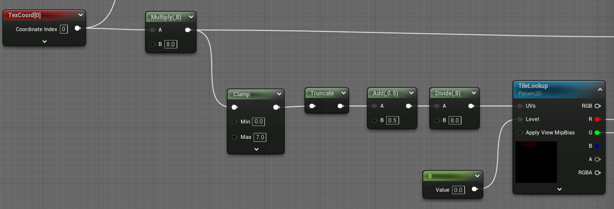
Here, we multiply our UV by 8, clamp it because we don’t want 8 as an actual value. Remove the fractional part. Add 0.5 to sample the center of our lookup texture. And then divide by 8 to get back to 0-1 range since we’re doing a normal texture sample here into our tiny 8×8 lookup texture. We must sample from the highest resolution texture LOD. So make sure to set the level to 0 and the MipValueMode of the texture lookup node to MipLevel (Absolute).
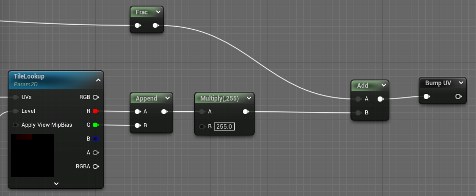
Frac (after multiplying our UV coordinates by 8) gives us the UV coordinates inside our UDIM tile. But we now need the UDIM coordinates that we read from our lookup texture. Those coordinates are in the Red and Green channels so we make a float2 out of it and we multiply by 255 because all values from a texture sample will be from 0 to 1 (these are pixel values, not uv). Since pixel values range from 0 to 255, we multiply by 255 and will get the integer value again. We then add the fractional part back in and that’s our UV for this tile. You can then use this as the UV for your texture sample. In the above image, using a bump map adjusts the uv a bit so I use that adjusted UV in all other texture samples.
So that’s rather easy. But there’s still one problem that remains.
Our virtual texture could be any size. And it won’t necessarily match the number of tiles in our mesh. So the LOD that the Engine will use by default will be the LOD of the UDIM texture. That size is off by 8 in our example. So it would be 3 LOD levels off. That’s not good.
What we need to do is compute the texture LOD level we want.
We need to calculate what our texture size is on our mesh if we were to render it at the highest resolution. Well, there are 8 tiles across. What size is each tile? In my case, they are 1024×1024. Rather large, but hey, that’s what virtual textures are for. So my “virtual” texture size is actually 8×1024 = 8K. This number can go beyond the 8K limit of Unreal Engine max texture size. But for every doubling, you lose one bit of precision. Luckily, most hardware uses several bits of sub pixel precision. It’s usually not important, but something to be aware if you start to use a huge grid.
Virtual Texture Size = Grid Size * Tile Size
There is a node in UE to compute the texture LOD to use.
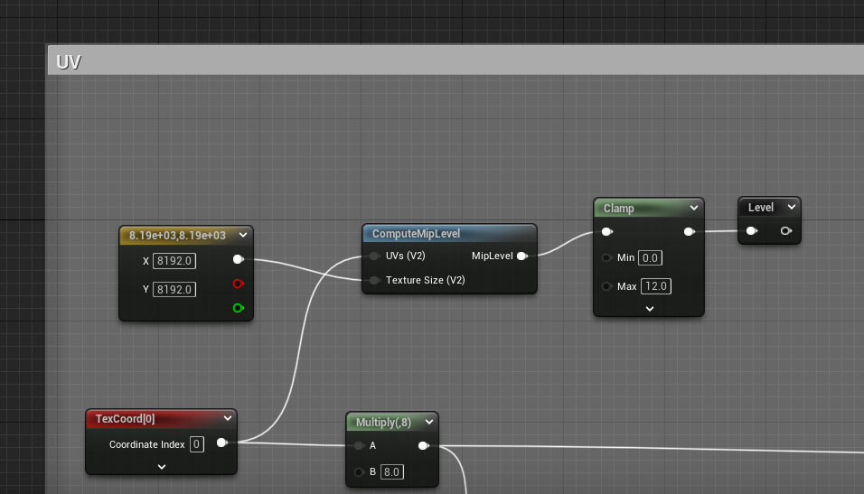
Above, we can see a constant with our computed virtual texture size and a ComputeMipLevel node. You shouldn’t need to clamp it. I just like to be safe. Then you use this level in all your texture samples except the lookup texture.
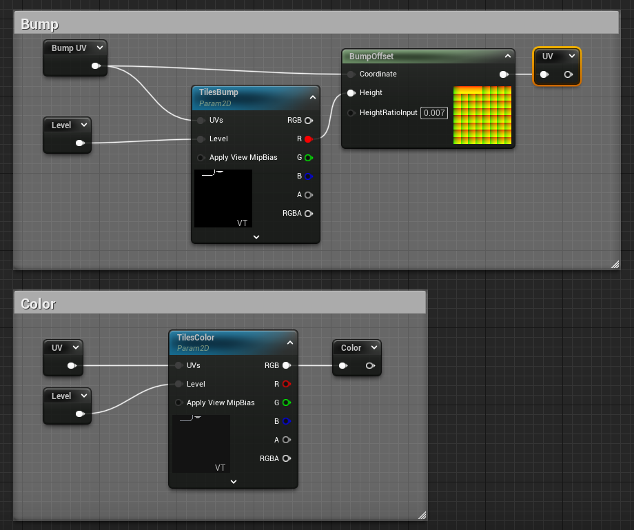
Above, we can see how to do texture samples. If you use a bump map, you use the UV you computed and feed the sample into the BumpOffset node. Make sure to set the appropriate range for the bump map. Is it 0 to 1, or -1 to +1? This will adjust the UV to create the impression of extra detail. I didn’t show the clamping of the output of the BumpOffset node. The integer part needs to remain the same. So one solution might be to bump the fractional part of the UV by itself, run it into a saturate node and then add the integer UDIM coordinates.
You then use this new UV into all other texture samples. An example is shown with TilesColor. The output Color node would hook up to the Base Color pin of the output node.
Ensure the Sampler Type is set to a Virtual type such as “Virtual Color” and “Virtual Linear Color”. Note the VT at the bottom right of the preview images. I use Virtual Color for the actual color texture, Virtual Normal for the normal texture and Virtual Linear Color for everything else. The lookup texture should use a regular Linear Color sampler.
If you don’t use bump map, then just use the computed UV (just rename “Bump UV” to “UV” in the example above) and use that as your UV.
Conclusion
I’ve seen way too many threads that ask how to do this with no responses. It’s a somewhat challenging problem, but Unreal Engine is up to the task. And once you understand the setup, it’s remarkably easy to do. UDIM file naming will automatically merge your tiles together. No need for cumbersome blueprint or C++ code to do that. No need to deal with borders and resampling your texture to odd sizes. Just do a lookup, replace the integer value of your UV and you’re done. Oh, and Mip Level computation, but there’s a node for that.
One last thing, remember to use a different lookup texture for each gridded mesh if you want a different pattern of tiles.
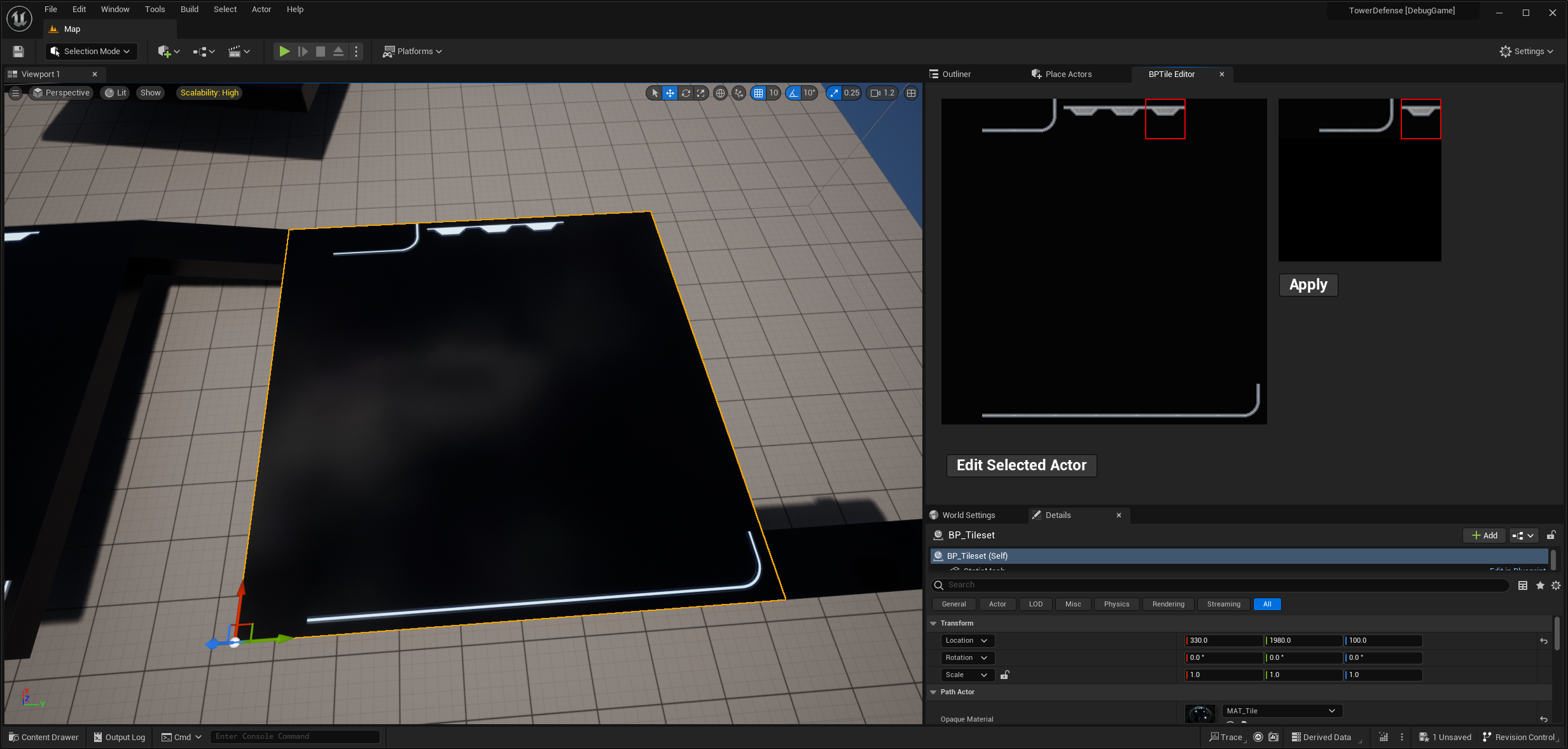
Here is my tile editor to let me choose what pattern of tiles I want on my grid. Unfortunately, I haven’t implemented rotating tiles yet 🙁 I’ll put rotation info in the blue channel. That part is left as an exercise to the reader 🙂
The Left area in the panel is what you see in the game. The right side is the set of tiles I can choose from. I hit apply to apply the selected tile (on the right) to the selected grid cell (on the left). I’ll need another button to rotate the grid tile and update the material to handle that.