Adding Custom Collisions in Unreal Engine 5

Have you ever wanted to add a custom collision to a static mesh you’ve already imported? Of course you have. But the only way is to add ECX_ named meshes to your FBX file and re-import. But then you can lose your settings, LODs or other things you had done. If you use multiple 3D software, you could lose the smoothing settings on your mesh. Yes, this is all avoidable. But it’d still be nice if you could just import a separate static mesh and use it as a collision mesh. The restriction that it must be a convex shape still applies. But there is a way.

We’ll go through an example.

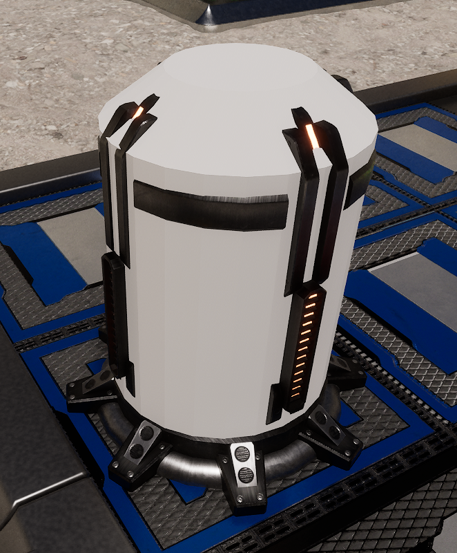
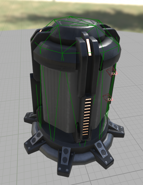
I have this fire tower that I already imported. I don’t want to mess with it and would like to just add a collision mesh to it.

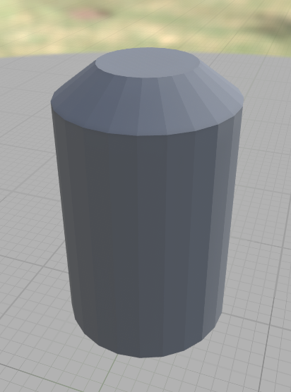
First thing to do is import your FBX file that only contains the collision mesh. This is my collision mesh. Fairly simple.

Objective is to use the geometry itself as the collision. But every single tool in Unreal Engine only copies the collision mesh. You can copy the collision mesh from one asset to the other. But you can’t use the geometry itself. Annoying, right?

So what we must do first is convert this mesh that we want to use as a collision… as the collision mesh itself. And the way we do that is by using the convex hull tool in the modeling tools. Don’t worry, it won’t be the wrapper type thing you see in the static mesh editor. It will be an exact copy.

What we do now is place an instance of your original mesh into a level. And then place an instance of your collision mesh at the exact same location.

I’ve done that here.

Now switch to modeling mode. This is in the dropdown at the top left of the editor where you find other tools such as landscape and foliage.

Select the collision mesh so that it is selected in the outliner.

For this step, it’s usually easier to make the original mesh invisible. So click the eye icon in the outliner on the original mesh to not have it displayed for the moment.

Select the collision mesh again.

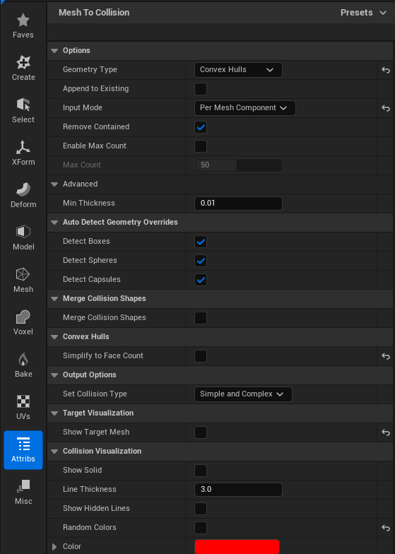
Go into the Attribs tab and select “Mesh to Collision”.

Set Geometry type to “Convex Hulls”.

Input mode should be Per Mesh Component.

Append to Existing should be unchecked because we want to overwrite the collision data.

Now for the most important setting.

Uncheck “Simplify to Face Count”.

This will make the convex hull have the exact same geometry as the underlying mesh.

Set Collision Type should be set to “Simple and Complex”. This will let us overwrite the simple collision and complex will continue to use the original mesh.

You can toggle “Show Target Mesh” on and off to see what’s going on.

Click Accept. It’s in the middle of the screen at the bottom.

Now open up your collision mesh into the static mesh editor.

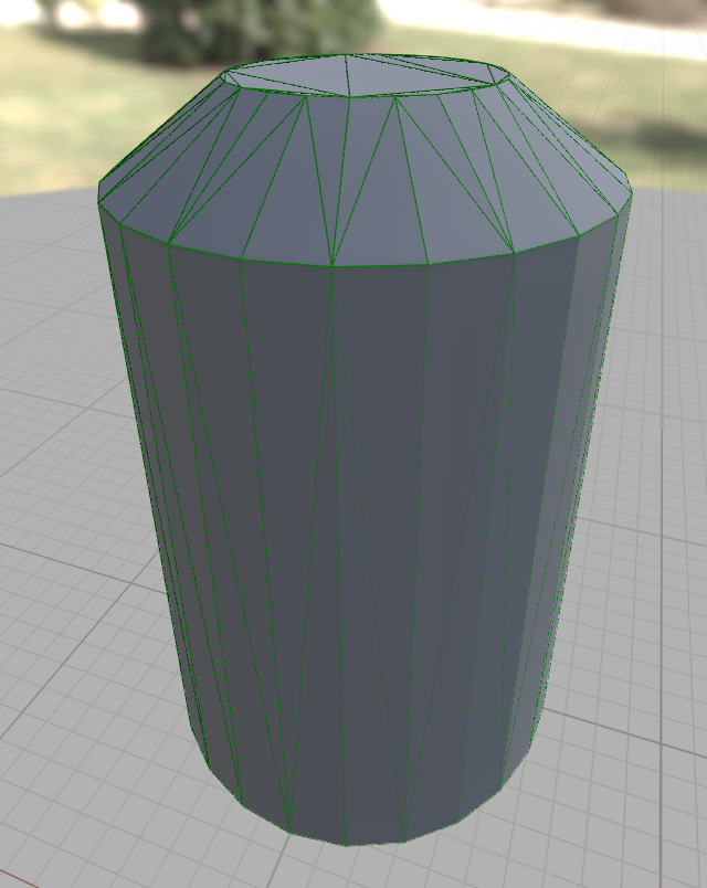
Under the eye dropdown list, check the “Simple Collision” checkbox. You can now see that the simple collision is the same as the original underlying collision geometry.

See the green lines? That’s the collision mesh. Save your mesh.

Now we can copy it to the original mesh. There are multiple way to do this. One way is using the “Copy Collision from Selected Static Mesh” menu option in the collision dropdown in the static mesh editor. But we’ll be using the modeling tools because there are more options here and we can do some interesting things.

Also, you may ask why you couldn’t just set the mesh to use Complex as Simple and copy the collision that way. I tried that. It doesn’t work. I tried almost everything. Nothing worked except the step above.

Back to the main view and still in modeling mode, make the original mesh visible again. We want to select the collision mesh FIRST. And then CTRL select the original mesh. In my case, I select the collision mesh first and then CTRL select the tower mesh.

Go into the Attribs tab again and we again select “Mesh To Collision”.

Since everything was already setup before, you can keep the existing settings that were used above and just click Accept and you’re good to go.

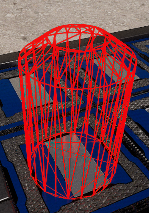
But let’s say your collision geometry has too many polygons. Mine has 140 polygons for example.

I’m now realizing this is bit too much for a collision mesh. No need to completely start over with a new mesh. The Mesh To Collision tool has a decimation feature built in (sort of). It’s actually reconstruction of the convex hull.

So check the “Simplify to Face Count” checkbox.

Now you can set the “Hull Target Face Count” to the number of polygons you want to use for your collision mesh.

I set it to 50 and it still looks good to me. You’ll have to play around with different values and see what works best for your geometry.

Now I have a 50 polygon simple collision mesh on my tower without having to add ECX meshes to by FBX and re-import or any of that stuff.

Hope this helps if you ever encounter this situation.

EDIT: After playing around with this some more, I found that you can skip the step where you set the collision geometry on the collision mesh. You can go straight to selecting both the collision mesh and the original mesh and using “Mesh To Collision” directly. The convex hull settings can be used the same as the last step and will work in one step instead of two. But if you want to save the collision mesh for whatever reason, both steps are still valid.

Also, wishlist my game on Steam:

RoboSiegeTD

Lighting Cheat Sheet

My previous posts on the topic were very wordy. So here, I want to have a quick summary of the technical aspects of lighting.

Lighting has 4 parts.

  1. Direct lighting and shadows.
  2. Indirect lighting known as global illumination.
  3. Reflections
  4. Ambient Occlusion.

Direct lighting and shadows

Direct lighting is done the same way no matter what pipeline you use. But how you do shadows will greatly affect all the rest of how you do lighting.

  1. Nanite + Virtual Shadow Maps
  2. Traditional Cascade Shadow Maps (directional light)

You must choose which one. Or if you want to use both (just not at the same time), you can set them up in your scalability settings.

Raytraced shadows will override both of these, but you must still choose which pipeline you want.

Virtual Shadow Maps

If you choose Virtual Shadow Maps, you must turn on Nanite even if you don’t use it. VSM is optimized for Nanite, but you can use it with non nanite assets. You’ll just have overhead penalty of both pipelines. If you only use Nanite (and no non-Nanite assets), then the traditional pipeline won’t be used at all and you can get some performance back.

VSM handles all shadows for you. And this is by far the simpler route to take.

Cascade Shadow Maps

If you choose Cascade Shadow Maps, you enter the world of the traditional pipeline and things get VERY complicated. But hopefully, this article will simplify a lot of it.

If you use a directional light, all shadows within the CSM radius will be under the control of the directional light. If you have other lights like spotlights within the radius, those will produce shadows one at at time, but the shadow budget is still under control of the directional light. The directional light is optimized to build all shadows within its radius at once. The number of CSM levels controls the resolution and hence blurriness of each level.

The radius of CSM is set with the property called “Dynamic Shadow Distance”. There are two such settings depending if your light is stationary or movable.

Beyond, this radius, you have three choices. But let’s list them in terms of distance.

  1. Closest: directional light + CSM
  2. Medium distance: far shadows OR distance field shadows w/ static shadows
  3. Nothing or static shadows

Beyond the CSM radius, you can choose either far shadows or DFS or nothing.

  1. Far shadows are like CSM, but further out.
  2. Distance Field Shadows use distance fields and will also use static shadows (static lighting) if you have baked them.

CSM + DFS is a common choice.

The distance is set on the directional light in each section.

Beyond this, only static shadows will display or no shadows at all. It’s usually too far away to see shadows anyways.

Global Illumination

Global illumination is when light bounces off an object and hits another object before hitting the camera. This is what causes shadows to not be completely black. It’s what allows emissives to shine their light onto other objects.

Here, you have 4 choices:

  1. Lumen
  2. Screen Space Global Illumination (deprecated)
  3. Lumen Lite
  4. None

Lumen is quite expensive, but is the best looking solution. In Unreal Engine 5.8, they deprecated Screen Space Global Illumination. There is a new Lumen mode called Lumen Lite which is twice as fast as regular Lumen. Lumen requires Distance Fields to be turned on and all your assets must have proper distance fields generated. You can go into the eye icon dropdown at the top of the viewport, then at the bottom of the list at Vizualize, then select Global Distance Field or Mesh Distance Fields.

Setting any of these up is done in in the PostProcessVolume under the section called Global Illumination.

To use Lumen Lite, you select Lumen and set sg.GlobalIlluminationQuality 1 or set it in your scalability settings ini file.

Screen Space GI is where only assets seen on screen contribute to indirect lighting. It is faster, but less accurate.

Reflections

The types of reflections you have is based on if you have Lumen on or off. This is set in the PostProcessVolume section under Reflections.

  1. Lumen Reflections (only available if Lumen GI is on)
  2. Screen Space Reflections
  3. None

You can only use Lumen reflections if you have Lumen turn on for Global Illumination as well. But you can always choose screen space reflections as well even with Lumen.

If you don’t have Lumen turned on for GI, then your only options are Screen Space Reflections or nothing.

Screen space reflections only use what is on screen, but look absolutely terrible. They cannot handle emissives properly. However, Lumen reflections are in many ways even worse than SSR. Lumen reflections are blurry and won’t do Niagara reflections at all. They just won’t show up. Now, if you use raytracing, you can get nice reflections. But if you intend on having your game look good on older hardware with Lumen Reflections, good luck.

Now, if you don’t use Lumen Reflections, you do have extra tools at your disposal that aren’t available to those who use Lumen Reflections. The first is Planar Reflections. These are by far the best reflections in the engine. And they don’t work with Lumen though it seems they’re trying. Remember to make these invisible if you use Lumen in your scalability settings as it will cause all Lumen GI to flicker like crazy even if you can’t see it, but has it’s Visible property set to true. Planar Reflections can use a specific list of actors to re-render to cut down the cost. It is expensive to use, but looks amazing and can do mirror reflections.

The other tools available or reflection captures with sphere or box reflection captures. These allow reflections to be used even if they are off screen. They should be used as static captures. You can use them as Runtime captures but it’s much more expensive.

Reflections tend to be a host of compromises regardless if you go with Lumen or not.

Ambient Occlusion

Ambient occlusion is when you have lots of nearby geometry that prevents light from going into these areas. This will create softer and darker shadows.

Here, you have several options:

  1. Lumen AO (on by default if you use Lumen GI)
  2. Screen Space AO (many use this instead of Lumen AO)
  3. Distance Field AO
  4. Ray Traced AO
  5. Baked AO

If you use Lumen, it already does indirect lighting so it already computes Ambient Occlusion. However, many people feel it’s not strong enough and manually turn on SSAO with r.Lumen.DiffuseIndirect.SSAO 1.

If you use Screen Space AO, these settings are configured in the PostProcessVolume under Ambient Occlusion. Note that these settings only take effect when SSAO is used. If you don’t use SSAO, they are ignored.

To use DFAO, you need to turn on distance fields and set your SkyLight to movable. If you use Lumen, this may not be available unless you use Lumen Lite.

To use Ray Traced AO, this is only available when not using Lumen. Lumen will use hardware raytracing through other means and use it for AO automatically. To enable this if you don’t use Lumen, you can turn it on in the PostProcessVolume under Ray Tracing Ambient Occlusion section.

Baked AO is used with static lighting and requires baking your lighting. This will be used when static lighting is used. I’ve only ever been able to see this used when all other AO methods are disabled. But maybe it can appear in other cases.

You can also do Ambient Occlusion with materials, but this is deprecated with Lumen and with Substrate. The new workflow is to just multiply your AO map with your diffuse (color) map.

Lighting with a roof using directional lights

In one of my levels, I ran into a problem. I had not planned out my lighting. In fact, I didn’t understand how lighting worked at all. If you use a directional light, that light takes over almost every aspect of lighting. It uses cascade shadow maps based on the setting on the light. It takes over the shadow budget for all other lights as well. I’m not using Virtual Shadow Maps. So I don’t know if the effect is the same, but my guess it would be because it has to do with direct lighting.

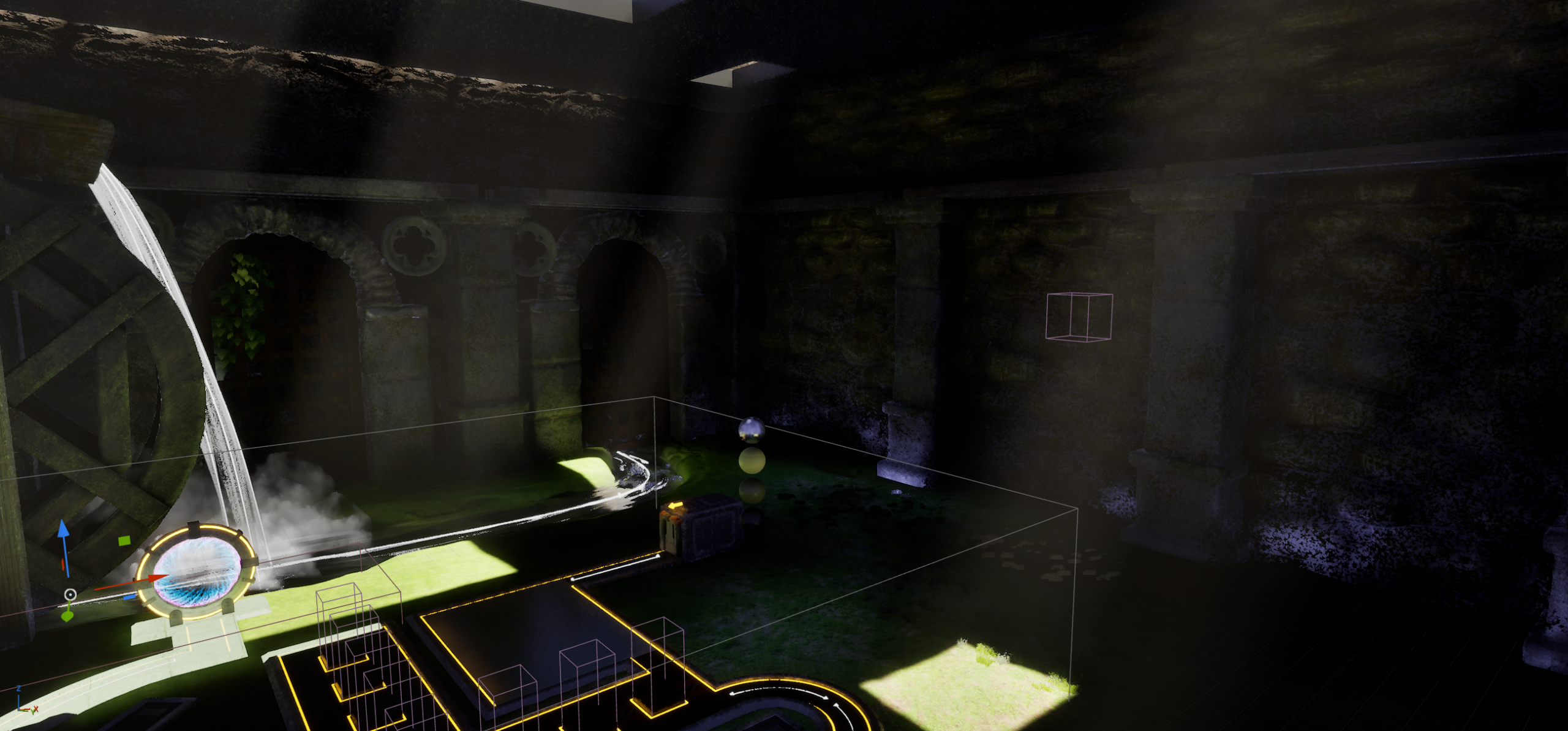
In one of my levels, I made it look like an abandoned courtyard inside a castle for giants. But the courtyard had a roof with holes. The holes were there to produce god rays or volumetric effect. Basically, you see a column of light beaming down. Like this.

You get these columns of light by increasing the Volumetric Scattering Intensity setting on your directional light. I bumped it up to 2 in the image above. It’s usually at 0.8 for a more subtle effect. But notice what happens to the level. It is quite dark. For the longest time, I thought I would have to remove the roof and just get rid of this effect. But I kept coming back to it because it was the original idea behind this level. Everything else was built around this idea of using god rays. The first obvious idea is to put in spotlights or other lights in the level. That does work. But you can only have 4 overlapping lights for static or stationary lights. Now, this is a very stupid statement. Why? Because back then, I didn’t understand how lights worked. Everything around the camera uses dynamic lighting. There is no scenario where the entire level isn’t rendered using dynamic lighting because everything is close to the camera. It’s a small level. If you don’t use a directional light, you could get static lighting to work, but that’s another topic. With a directional light, everything is dynamic around the camera. The distance is set in the directional light.

Ok, so if it’s dynamic, then using spotlights is fine, right? Well, no. They don’t render using the same system as the directional light. Every object is rendered separately and shadows are dynamically created individually unlike the directional light that does everything in one go. Directional lights are MUCH cheaper than other types of lights. Also, the shadow budget is controlled by the directional light even though it’s a different light.

There’s a MUCH bigger problem though. The shadows from the directional lights tend to override anything from other lights. Directional lights are the king of controlling shadows. So putting lights inside the level will help somewhat, but it will get drowned out up close to the enemies and towers. Said plainly, lights don’t like it when they compete with each other. We have the main light casting a HUGE dark shadow over everything and the other lights are trying to counter that. The engine really doesn’t like that. If you just want a light on the wall or some extra illumination, that’s not too bad. But shadows on moving actors is going to be a nightmare.

I tried a LOT of things. Nothing worked. One example was trying to make the roof semi transparent. That was a disaster.

Then I saw a feature I don’t think I’ve ever seen mentioned before. It’s apparently meant for the render queue, not for games. In the directional light, there is an option called “Cast Shadows from Cinematic Objects Only”. What we do is add a second directional light. You need to set the Forward Shading Priority to 0 (or lower than the main directional light) so as to not cause conflicts. This setting is to tell the engine which light controls the shadow budget. You need to set the second directional light to movable. This isn’t a problem because everything nearby is using dynamic lighting anyways. This light should have the checkbox for Cast Dynamic Shadows and no other types of shadows. All other types of shadows should not be checked. Also turn off Atmosphere Sun Light on the second directional light.

Now you get lighting inside the level. But there are no shadows from this light at all. To get shadows, only actors that have Cast Cinematic Shadow enabled will cast shadows. And those actors must be movable. Again, I originally thought this would take a performance hit because I had to make my actors movable, even for static walls that I wanted to cast shadows. But as I said, anything near the camera is rendered dynamically anyhow when you use a directional light. For the walls, I added fake proxies. Just big rectangle shapes behind the walls and enabled Cast Cinematic Shadows. And I set this flag on all my towers and enemies. I then looked at everything in my level that I wanted to cast shadows and turned on that flag as well.

As I was writing this article, I noticed that my screenshot above had some blue lighting at the bottom of the walls on the right. I went looking and found that this is the scattering color of my fog component. I’m using an ExponentialHeightFog. So I turned it white, but it was still visible. So I changed the end distance to be 500. This limits the scattering distance and it solved the issue. So writing this article helped solve a problem I didn’t even notice until now.

Anyhow, this is how you can get get extra lighting in an enclosed area if you use directional lights. Use the Cinematic shadow feature.

Wishlist my sci-fi tower defense game on Steam or Epic Store

RoboSiegeTD on Steam

RoboSiegeTD on Epic Store

Thoughts on Parallax Occlusion Mapping (POM)

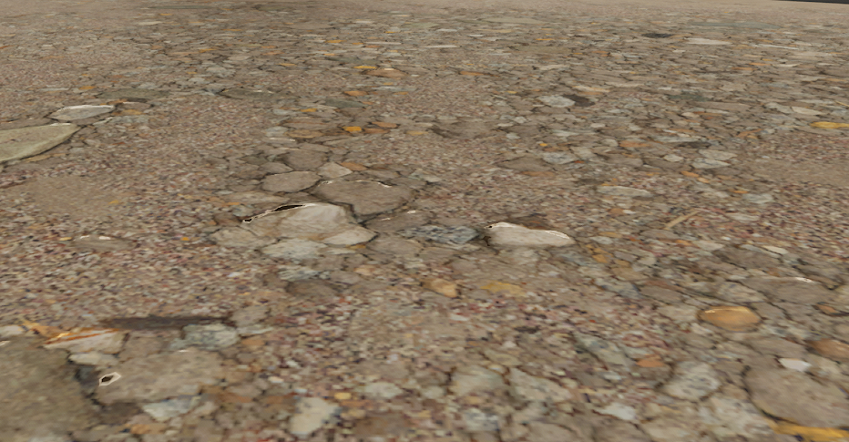
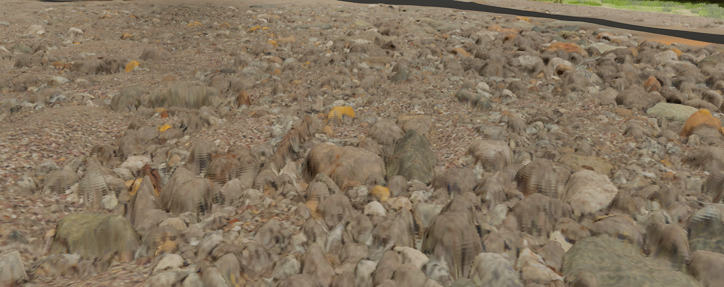
Parallax Occlusion Mapping is a method where the pixel shader does ray marching to properly offset the UV coordinates to fake depth in your materials. Basically, it makes things look more 3D even though it’s still flat. Usually, normals do the heavy lifting. As in this example from above, these rocks look pretty good.

But when viewed flat on, it looks quite flat.

But if you use Parallax Occlusion Mapping, you can get something like this. Note that this is greatly exaggerated for effect.

To make this work, it needs a custom HLSL node that loops 8 to 64 times to do ray marching. It’s not raycasting, but just seeing if anything is occluding it by sampling a displacement map in front of the current texture coordinate on pixel at a time. If it finds an occlusion, then it returns that offset and that’s what’s displayed on screen. So it makes it look like your flat plane actually has geometry. With the help of normals, it looks really good. And yes, it is costly, but if it’s only on a few assets, it’s not bad.

So far, nothing new here. Why this topic?

Well, I wanted to do something a bit bonkers. I have a virtual heightfield mesh already for the terrain. It can take a height maps and add displacement already. But was it good enough? I had to find out. So what if we turn off displacement and use POM instead? There was just one catch. I was using Runtime Virtual Textures (RVT). What is RVT? It’s basically dynamic megatexturing. It’s where you draw into a big and sparse virtual texture one tile at a time as you need it as your move and turn the camera. But the next time you need that tile, you don’t use the original material, you just grab the textures from the RVT and use it directly on your material output node. This can really speed up rendering.

Still nothing new.

Well, for POM to work, you need to pass in a texture object. RVT doesn’t allow itself to be treated as a texture object. Ok fine. I decided to modify the custom HLSL to sample the RVT directly in the custom code. Only problem is this isn’t supported. Not only that, but I needed to use derivatives to select the LOD. These instructions are DDX and DDY. You can use them on any variable and it tells you what the value is in the neighboring pixel’s pixel shader. All video cards render 2×2 pixels at a time. So you can ask it what any variable is for adjacent pixel shaders. That means you can compare UV coordinates between pixels on screen. So if the UV’s are one texture pixel apart, then you use the highest LOD. If they’re 2 texture pixels apart, you use LOD 1. If they’re 4 pixels apart, you use LOD 2. If they’re 8 pixels apart, you use LOD 3 and so on. It’s the log2 of the texture pixel distance to find the LOD. You can use an average with the adjacent vertical pixel.

When looking at how to sample from RVT, there is no function to sample with DDX and DDY values like there is for regular textures. So how to do it? I implemented a material graph with a single lookup to the RVT using DDX and DDY and then looked at the HLSL code it generated for my material. I then copied the code and modified it to use my derivatives. It’s a very long mess of code. And the values (uniforms aka. values passed to the GPU from the CPU) needed to sample from the RVT are hardcoded indexes. IOW, they are magic numbers as they are generated by the engine. So if I change anything, I have to update a few indexes. Very fragile. But I got it working.

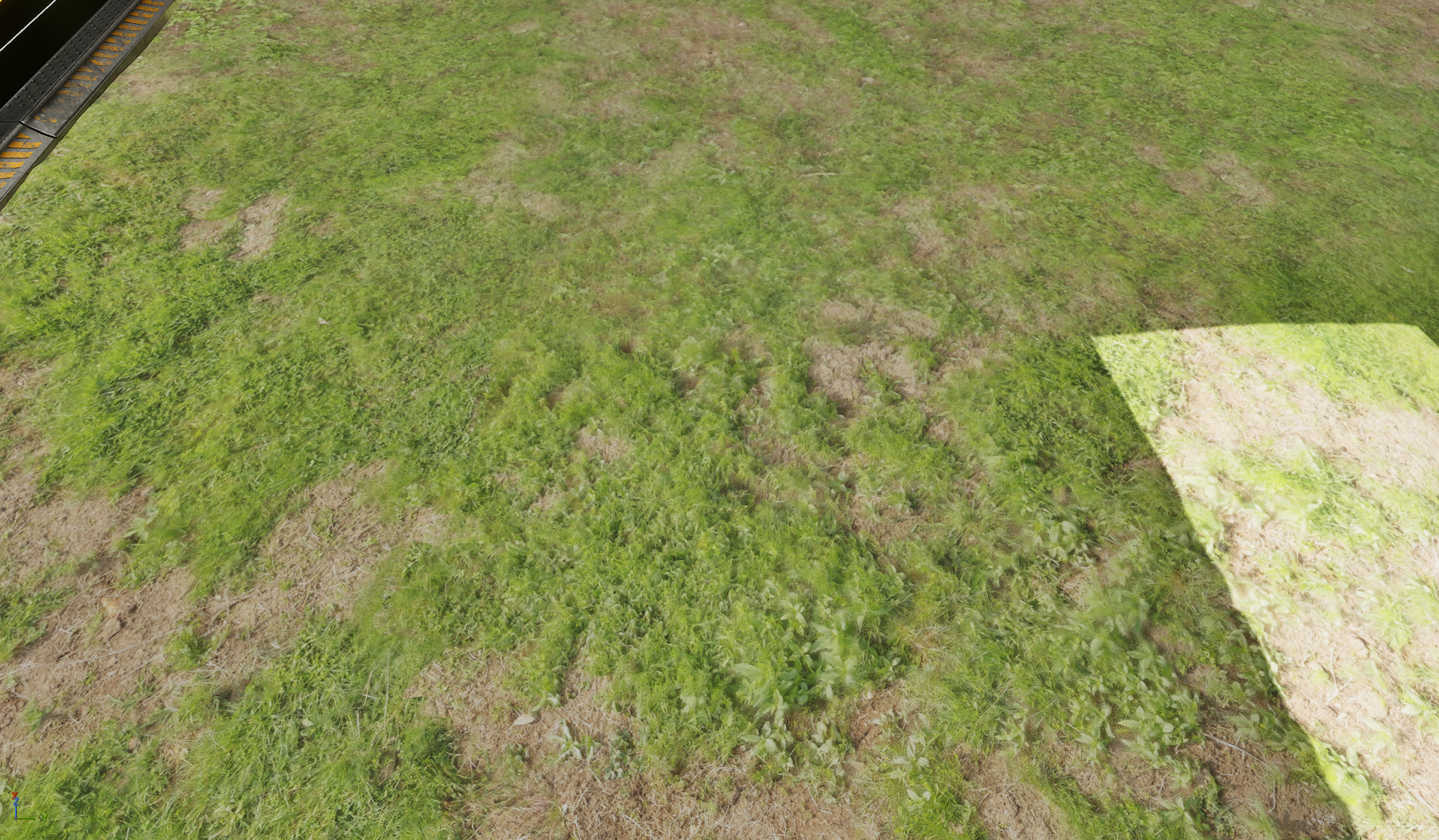
Here is an image with three separate parts. Flat, Virtual Heightfield and Parallax Occlusion Mapping. Can you even tell where I split the images?

On the left is flat. In the middle is POM. On the right is VHFM. And yes, they are all slightly different from each other for the full image.

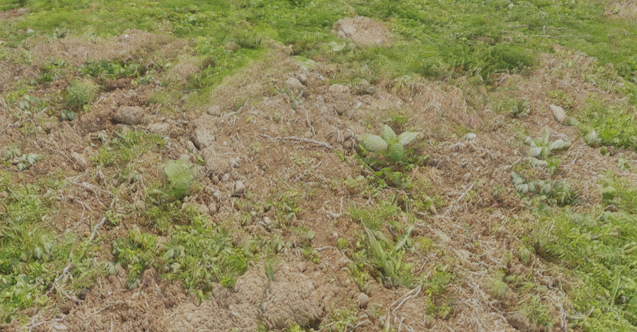
Up close, POM can look really really good. Here’s one example:

But no one zooms in that close to admire the grass. As soon as you zoom out a bit, the difference isn’t that great anymore. Now, POM is indeed superior. No question about it. But is it worth it? ABSOLUTELY!!!#$@$@#@!! Hell yes! What’s the point of optimizing your game if you can’t bloat it down again with cool effects that you’ll hardly notice?

The answer should have been a clear no. But I’m not so sure. I’ll probably remove POM simply because it’s so fragile when used with RVT. I’d never be able to maintain it. The point is that while some projects do get bogged down with visuals, adding a few effects for fun isn’t a bad thing. I also think there’s a cognitive bias at times. Parallax Occlusion Mapping sounds cooler. So it must be better.

I don’t really have a point other than I don’t think POM is that much better than VHFM. And I wanted to rant about wanting to use a feature that I can’t justify 🙂

Steam Store Page is LIVE!!!

My Steam Store page is live. Please wishlist it if you’re interested in my game. I’m currently setting up a playtest. So if you’re interested in helping and testing the game, there will be a button that will request to join the playtesting team. It should be up very soon. I’ll also have a trailer up on the store page soon as well.

Robo Siege TD Store Page

Corrections on Lighting and How to use DFS on Skeletal Meshes

My last post on lighting wasn’t 100% accurate. I left a correction so I think that covers the biggest mistake. A lot of the info on each specific topic was good, but how they worked together was incorrect.

I just want to recap how shadows are computed. And Lumen doesn’t do direct shadows so it doesn’t matter if Lumen is on or off.

If you use Nanite, you must use Virtual Shadow Maps and you don’t need to worry about all the other systems. It is much slower, but if you only use Nanite, the traditional pipeline is not used and you can gain some speed back since each pipeline has overhead. If you use both is where most games get their framerate down. Use the traditional pipeline (no VSM and no Nanite) or use Nanite (which requires VSM).

The VSM and Nanite pipeline is obviously quicker for development. No LOD’s and no shadow setup.

Now let’s look at what the traditional pipeline is for shadows.

If you use a directional light (stationary or movable), then within a certain radius that you can specify on the light will produce Cascade Shadow Maps (CSM). These take over ALL shadows affected by the directional light. So if you have baked lighting, CSM will override those.

For other lights, it doesn’t work this way. For those lights (like spotlights, rect lights, point lights, etc.), when you are very close up (as in hundreds of cm and you cannot change this distance), it will use per object shadows. CSM does the same thing, but for all objects at once in an optimized fashion and you can set the number of quality levels to use with the best quality up close. If the object casting a shadow is a little further away from the camera, then it switches to an fallback mechanism that you have set on the light. If your light is static or stationary, it will use baked static lighting for static objects. For everything else, it will use Distance Field Shadows if you have it turned on. If you don’t have DFS turned on with your light, then it will continue to use per object shadows.

All this is true ONLY if you don’t use a directional light. Even if you have a directional light and you turn Cast Shadows off, nothing in the last paragraph is true. Directional lights override all shadows even if Cast Shadows is off. Only if you turn intensity to 0 on the directional light will other lights revert to their original behavior.

With directional lights on and shadowing distances set to zero, even with Cast Shadows off, VERY strange things will happen. None of your other lights will work correctly. If you use directional light, the only reliable way to turn them off is to set the intensity to 0.

When you use directional lights and you set it up properly with a non zero intensity and set up a proper CSM distance, etc. the directional light controls the shadow budget for your entire scene. If you move the camera back and you have a spotlight that is far away, the directional light can just start telling the spotlight “No more shadows for you” and spotlight shadows will just suddenly vanish. You can use the command r.Shadow.FadeResolution and set it to a lower number than the default 64 to keep the shadows around longer, but it’ll eat your budget somewhere else. Even CSM distance won’t help you here. The shadow could be well within CSM range and it can still make shadows disappear. The directional light is king. It rules all shadows. If you use r.Shadow.FadeResolution, you may also want to set r.Shadow.MinResolution to be at least half of FadeResolution. MinResolution is the resolution at which the shadow is removed. FadeResolution is the resolution when it starts fading. Setting FadeResolution automatically lowers MinResolution to at least the same value. But this means no fading. The shadow will just suddenly disappear.

As can be seen, just getting other lights to work with a directional light is a pain. And we haven’t even gotten to what happens beyond the CSM range. Here, you have three options.

  1. Static baked lighting (only on static and stationary assets and light must be static or stationary)
  2. Distance Field Shadows (works on everything except static lights)
  3. Far shadows

You can only choose one of DFS or Far Shadows. You cannot use them both at the same time. Baked lighting can be used in combination with either of those. So if something has baked lighting beyond the CSM range, it will use that. If not, it will use either DFS or Far Shadows. If neither of those is enabled, there are no shadows.

Distance Fields are like voxels. Movable objects can produce distance fields. So for far objects, these are great for producing shadows on both static and movable assets. Except they don’t work on skeletal meshes. The workaround I’ve used is to create invisible proxy meshes that cast hidden shadows. In order for it to not be used within the CSM range, I used a masked material and just set the opacity mask to 0. Within CSM, it will look at the material. But beyond CSM, the distance field generation does not look at the material at all. So the transition from CSM to DFS is 100% smooth. You can’t tell there is a transition at all. This is one of the weirdest hacks I’ve ever seen in Unreal Engine. But it works perfectly.

Far shadows are the alternative to distance fields. Far shadows are like CSM, but further away at lower resolution. That’s it. Not sure if it’s better or worse, faster or slower. I haven’t really tried it much. It does work and should work with skeletal meshes since CSM works with skeletal meshes. But I’m not sure.

With all of that, it’s easy to see why people would just use Virtual Shadow Maps. You deal with none of this. It handles all shadows for the entire level. It does reduce framerate with lots of camera movement, especially camera rotations and people have had issues with cache invalidation not happening quick enough. There are some settings with that. VSM does have quite a performance hit overall. And you must turn on Nanite. But like I said earlier, if you only use Nanite, the overhead for the traditional pipeline disappears and you can get some of the performance back.

It’s easy to see why studios are preferring Nanite and VSM over traditional workflows. And if they use Lumen as well, they now need an upscaler like DLSS (or even frame generation) to bump up the framerate.

Speaking of Lumen… now that I’ve fixed all the lighting in my game, I’ve noticed something quite drastic.


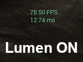
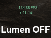
Now, 80fps with Lumen on using an old 1080Ti is really really good. 1080Ti is about equivalent to 3060, but no ray tracing. But you know what’s better than 80fps? 135fps! And I really can’t tell the difference between Lumen on and off most of the time. The most significant difference isn’t Lumen GI, but rather Lumen reflections. Even though they are blurrier than screen space reflections are planar reflections and they don’t work with Niagara effects, they are consistent, don’t have artifacts, and generally look good and make the emissives that I have on the towers and other assets look really good. The reflections on the towers look a lot better too. But is it worth half my framerate?

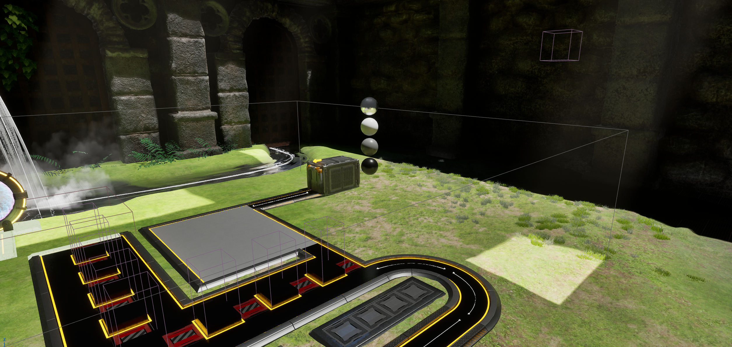
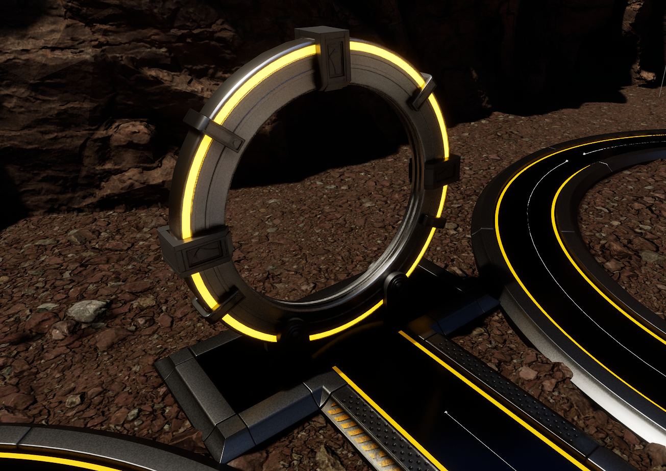
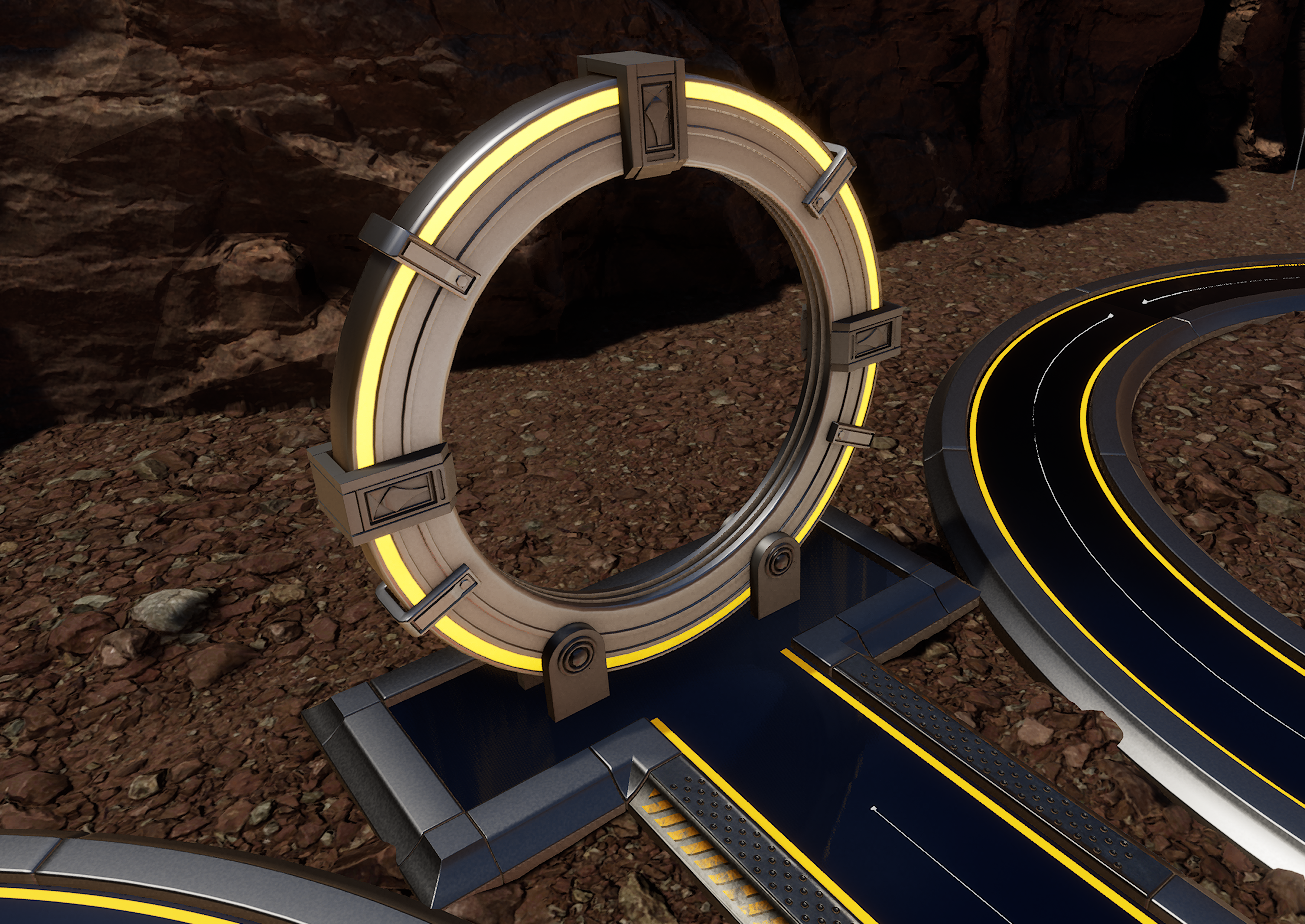
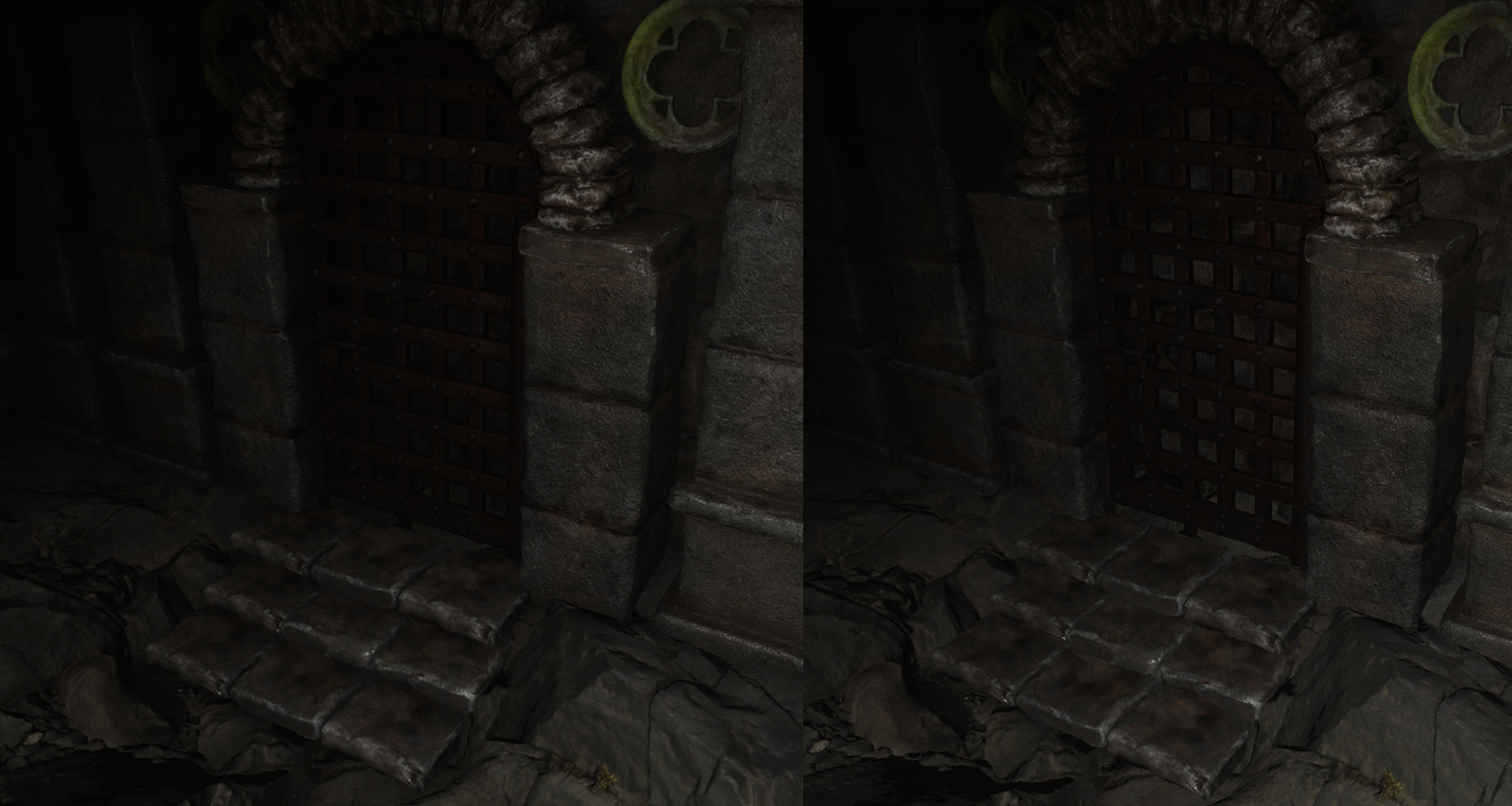
Here’s the difference with Lumen on and off. I tried to find something that made Lumen look better and the biggest difference. I also want to show off my new gate. Note that this is using default Lumen reflections and default Screen Space Reflections (when Lumen is off). In the game, I have custom reflections for both that make the niagara effect show up a lot better.

With Lumen:

Without Lumen:

The brightness and contrast can be adjusted. Currently, the user has the option to select Lumen or not. But will a gamer really know to do this? I added a checkbox to make it easier, but I worry that people won’t know what the best settings are. And is this really something I want to keep in the game at the expense of half the framerate?

As for the rest of the game, I only have levels left to do for the most part. There’s still integration with the Steam and Epic store API’s to do. But all the in game programming is done except for one bug with the carrier tower that I will be fixing shortly. All the issues with lighting are resolved. New assets have been added (new gate, new door and new sound effects). French language has been added. The game is very well optimized as can be seen above. I have several levels to do for the main campaign. And I want to add 5 alternate methods of playing. Things like fixed starting income (no income during gameplay), only rank 1 towers, limited number of towers, no interest, infinite, one of each tower before building a second, etc. Haven’t chosen which ones yet, but these are easy to implement. After that, I’m thinking I may add some bonus levels that all get unlocked at once after the main campaign.

Still a bit of work to do, but all the difficult stuff is done. Next task is to start cranking out levels and after that I should be close to release.

How Lighting Works in Unreal Engine (or What I Wish I Knew When I Started)

Lighting in Unreal Engine is a pain. Not that it’s terrible, but it’s difficult to know what to use and how to use it. You have lots of things like Lumen, reflections, shadows, distance fields, etc.

The first thing to understand is that direct lighting is only done one way. So whether you turn Lumen on or off, it doesn’t matter for direct lighting. That’s the easy part.

Next is shadows. If you use Lumen, you turn on Virtual Shadow Maps and you’re done. Only lights that are set to stationary or movable will be used. These are dynamic lights and shadows are created in real time.

If you don’t use Lumen, you can still use Virtual Shadow Maps for dynamic lights. But you can bake static shadow maps for static and stationary lights (on static actors).

Let me stress this. LUMEN DOES NOT DO DIRECT SHADOWS!!!

If you look at scalability settings for global illumination settings, Lumen is used for Epic and High settings. Lumen is turned off for Medium and Low settings.

So far, none of this has anything to do with global illumination. Global illumination is what happens with secondary bounces of light rays. So if you don’t use Lumen, baking lighting will also generate these secondary bounces and bake them into shadow maps for static actors. You won’t get anything with movable actors unless you use Lumen or fake it somehow with Ambient Occlusion maps (more on that later) or use screen space global illumination.

Secondary light bounces are what causes a room to be lit up even though there is no direct light inside. The light comes in through a door or window and residual light bounces will make it so you can still see inside the room. This is where Lumen really shines (pun may or may not be intended). And because secondary bounces can be blocked by meshes, you get secondary shadows for “free” with Lumen. So Lumen CAN do shadows, just not direct lighting shadows. And I’ve seen professionals in Unreal Engine try to tweak Lumen settings to try and get better direct shadows.

Another thing to know about Lumen is that it uses distance fields. What are distance fields? They’re like coarse voxel representation of your scene. It does traces against these voxels for secondary lighting. It also uses these for reflections (more on this later as well).

Is it getting complicated yet? We’re not even close to halfway done.

If you’ve ever used spline meshes, these don’t work with Lumen because spline meshes don’t create distance fields. Why? Because the mesh is distorted on the GPU. So on the CPU side, it has no clue where the mesh actually is and distance fields are turned off internally. You can still get some global illumination but it likely won’t be accurate.

One thing I really wish I knew before is that Lumen has a range. There’s a setting for this range. So what happens beyond this range for secondary light bounces? It uses screen space global illumination. IOW, only what can be seen on screen will cause secondary light bounces. So as things move off screen, you’ll see secondary shadows suddenly disappear. You can see some popping or flickering of object brightness.

But this too has a range. What happens beyond this range? Then indirect lighting simply turns off.

If you have hardware raytracing and you have built HLOD, you can greatly extend the range that Lumen will work in by enabling Far Fields. I’m not getting into HLOD here as that’s a topic of its own.

If you don’t use Lumen, there is also a Lightmass Importance Volume for indicating which area is more important. But what about indirect lighting on movable objects? For that, you have to use screen space global illumination. It will only use what is on screen. It actually looks decent. But it’s limited in what it can do and is prone to visual popping as things move off screen.

There’s a lot more to all of what was mentioned above, but we’ll move on to reflections.

Reflections are a complete disaster in Unreal Engine. Avoid reflections like the plague if you can in Unreal Engine. I made the mistake of thinking reflections worked. They don’t.

Lumen will do its own reflections. They’re bad. They’re blurry, out of focus and just horrible. You can turn on something called “Screen Traces”. These look AMAZING… when it works. It doesn’t work on any Niagara effects. And it doesn’t work on anything translucent. There are some special cases where it will kind of work, but only on one side… and that’s kind of useless if it’s translucent.

In my game, I have a gate with a niagara effect in the middle. So how do I get reflections of the niagara effect if you use Lumen? I had to get my niagara effect to write to a render texture. Then I have a reflection plane with a material that can take this render texture and draw it at the appropriate location to make it look like a reflection. Use this as a decal so that it gets drawn only on specific actors. It requires a LOT of setup and it doesn’t look all that great.

This is a Lumen reflection. Notice the lack of reflection for the niagara effect. Yet the yellow/orange emissive ring is reflected. (And yes, I’m thinking of redoing the gate asset, but this is good as an example)
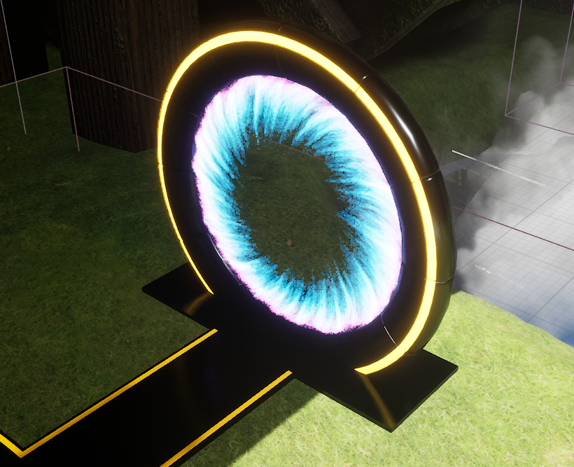
Here it is with a proxy reflection. This is a nightmare to do. Don’t do this if you can avoid it.
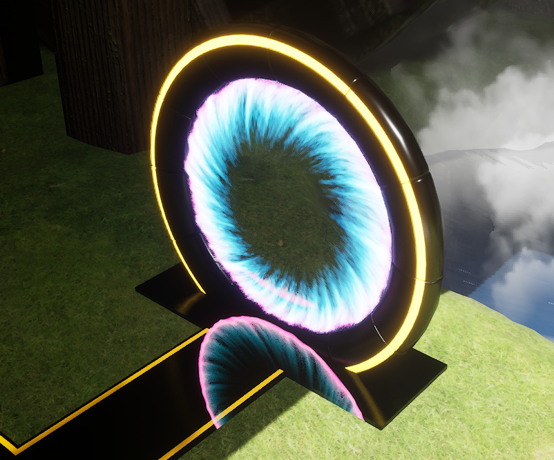
One thing you’ll notice is that the purple area is way to strong. This is because that area is actually inside the ring when looking at the main (non reflected) asset. I could probably clip the ring or something, but I can’t be bothered.

In any case, what the above image is showing is a flat plane on the ground set up as a decal that renders the render texture in real time at the right location.

But if you don’t care for translucent assets to be reflected, Lumen with screen traces is the way to go.

Finally, what happens if you don’t use Lumen? How do you do reflections then? Well, you have 3 options that can all work together.

First, you can use Screen Space Reflections. This is available with Lumen BTW. But the problem is that this looks HORRIBLE!!! It’s even worse than Lumen reflections when it comes to, well, anything. Not just translucent objects, but everything looks bad. It has a tendency to do streaks as well. Like this:
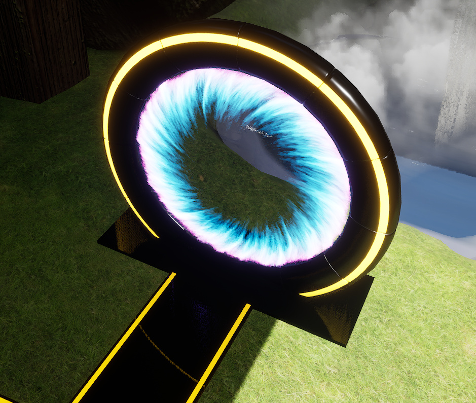
What is that even? You can see the yellow/orange ring is completely distorted. And while the niagara effect isn’t seen in the reflection, it isn’t because it isn’t being reflected. It is. It’s just the distortion is so great that it’s no longer on screen. I just couldn’t find a way to display it, but it will at times render. And it is HORRIBLE!!! It is completely distorted and streaky. You can’t even tell what it is.

Said plainly, screen space reflections just don’t work… for anything.

Second option is for static scene. You can use reflection captures all over your scene and they will show up in any reflective surface. Doesn’t work with movable object though I think it may be possible to have these update every frame. But they’re very costly to update. They will tank your framerate if you use them this way. For a static scene, they’re free and they look great. The only downside is that they only reflect semi far away objects. They don’t reflect objects beyond it’s attenuation radius. And they don’t reflect anything close to a reflective surface. They’re great to just make something look like metal for example, but not for actual reflections where you need to see what’s there. For example, you can’t reflect the ground with these captures because the ground is way too close. However, something in the sky could reflect the ground because it’s far enough away.

So how do you get close up reflections? There is a way. These are reflection planes. These are incredible! They look perfect. But they render the whole scene again for each reflection plane you use. Just by adding one, this can cut your framerate by half. But in practice, all the assets are already on the GPU, so the cost isn’t as high as that. These also support only rendering objects in a list. In my case, I have a reflective door and only want to reflect the ground and some tiles in front of it. I add those objects to the list and I have perfect reflections. You can also render at reduced screen size for even faster performance.

These are great!!! I wish I knew about these a LONG time ago.
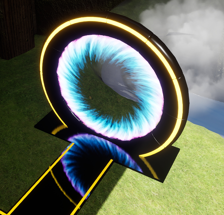
These reflection planes update in real time and render the whole scene (or the list you provided). So it’s not limited to what’s on screen. And setting them up is quick and easy. Oh, and they work with EVERYTHING!!! Niagara, emissives, everything!

What’s really annoying is that none of the reflection captures work with Lumen. Only Screen Space Reflections work with Lumen and those are garbage.

Here’s the rundown:

When using Lumen
1. Enable distance fields
2. Enable Virtual Shadow Maps
3. Recommend Lumen Reflections with Screen Traces.

When not using Lumen
1. Use Screen Space Global Illumination
2. Use Screen Space Reflections if you must have reflections on movable objects, but otherwise try to not use SSR at all.
3. Use copious amounts of spherical reflection captures. They’re free.
4. Use planar reflections for really reflective surfaces if you can limit what it renders. Also great if you must have a mirror effect.

And I didn’t even get into ambient occlusion.

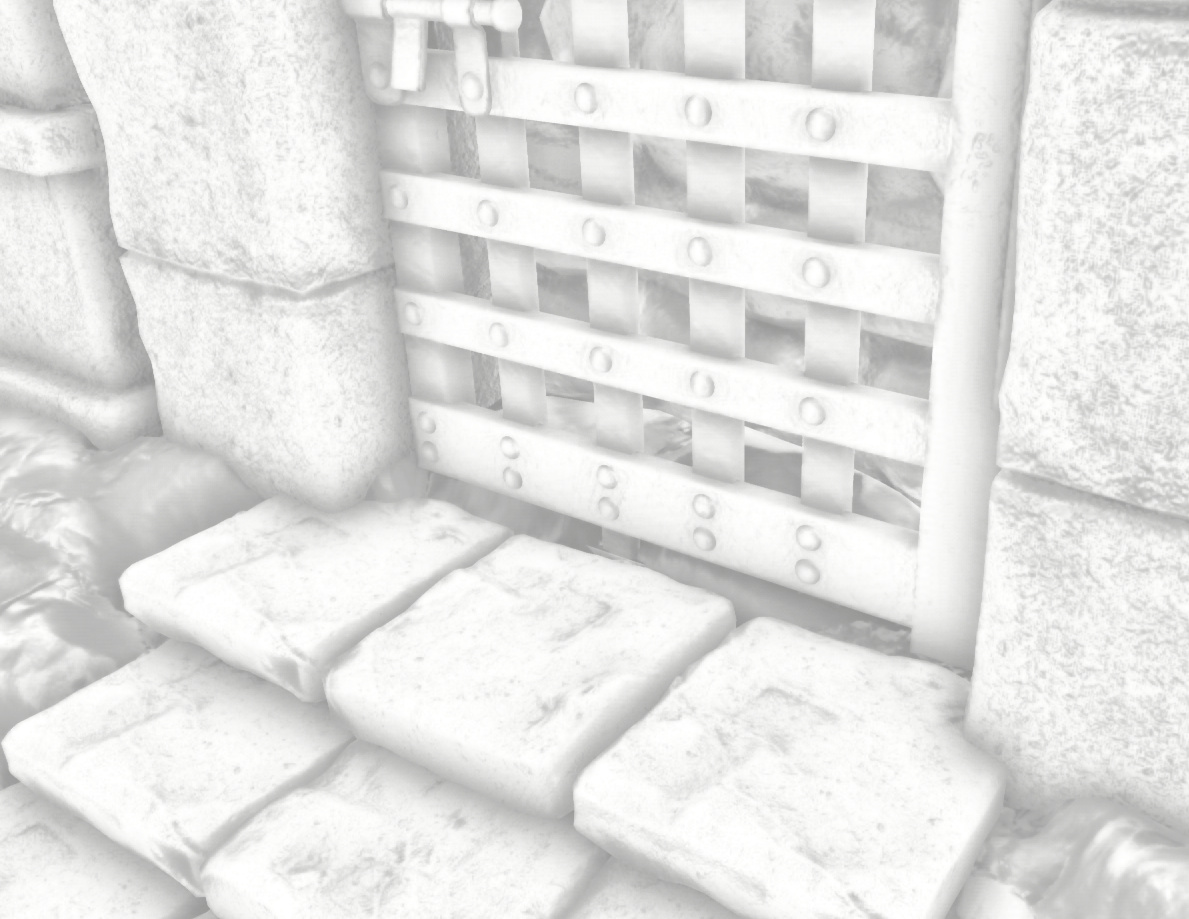
What is ambient occlusion? It’s just that small recesses, cracks, insets, etc. are darker than surrounding areas. Probably easier to see with an example.
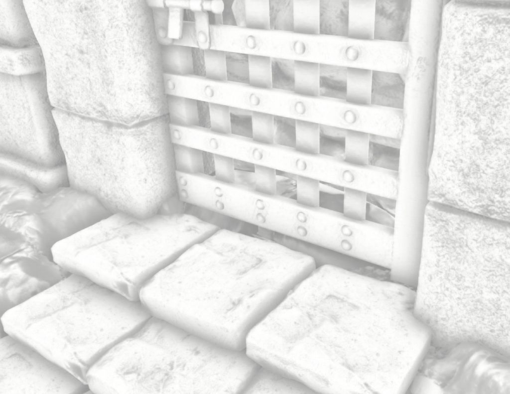
This is a display of ambient occlusion. So you can see the areas between the rocks that make up each step is darker. You can also see the area on the gate where the bars intersect is darker as the light has more difficulty getting in those corners. The entire scene will be made darker as indicated.

In the following image, AO is on the left. No AO on the right. You can see that it adds more details and makes the scene look more natural.
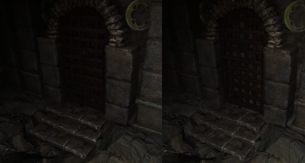
Ambient occlusion is too big a topic. For simplicity, I’d recommend just turning on screen space ambient occlusion. This works with and without Lumen. Lumen does its own ambient occlusion, but I find the screen space version looks richer and more detailed. Note that just because the ambient occlusion view shows all white with Lumen doesn’t mean there is no AO. It’s just that Lumen does its own thing. Perhaps a future version will show Lumen AO. And for objects further out, you can also use distance field AO.

You can also have AO directly in your mesh’s material. There are tools in Unreal Engine to bake AO to a texture so you can use it in your material. Both Lumen and non lumen lighting will use material AO. In my game, when the towers lift out of the floor, the yellow pit is drawn using baked AO. The reason is that light can’t get down there. It’s below ground and the yellow pit is drawn in the translucent pass, so lighting doesn’t work well there anyhow. By baking AO, it looks like it has proper lighting.
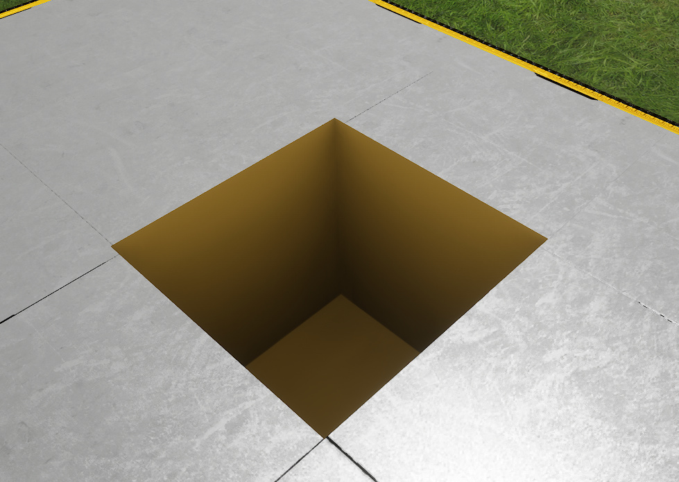
There is no lighting in the pit. It’s all done with an ambient occlusion texture in the material. A small detail. Yet one that adds a bit more depth 🙂

That’s it for now.

***UPDATE***

I learned a few more things about shadows. Virtual Shadow Maps were created specifically for Nanite. But they can be used with non Nanite meshes as well. Still, the developers at Epic decided that if you turn off Nanite in the project settings, then you can’t use Virtual Shadow Maps either despite selecting it. After turning Nanite on, I got at least a 15 fps drop in my scene. That is a huge hit. The alternative is to go back to cascade shadow maps. These don’t look as good, but honestly, it’s not that different. The only issue with Cascade Shadow Maps is that you have to tweak the settings a lot more to get something you like. Oh, and I said earlier that Lumen requires VSM. It does not.
September 2024 Tower Defense Game Update

A little update on what I’ve been working on. Still have several levels to do, but I am working on it more regularly lately. The main objective now is to have the game fully functional so I can produce a demo. That means all UI done. Settings screen with keyboard and controller bindings are done. Volume control is done. Backstory and Credits screen is done. I wanted alternative ways to play the game (only level 1 towers, fixed points, limited number of towers, 99 waves, etc.). Those won’t be done yet. That part will be left for after the main game is complete.

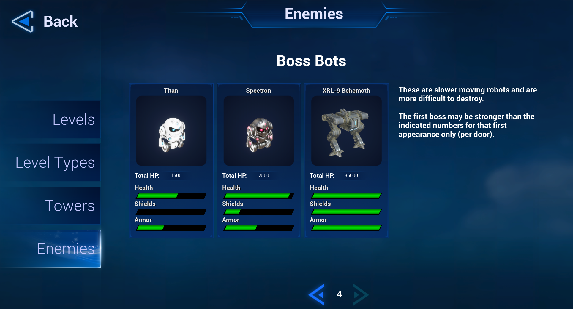
A lot of Quality of Life enhancements have been included (more on this below including screenshots). And some details have been added like animations in the preview screens. Also added an enemy preview screen.

Enemy Preview:

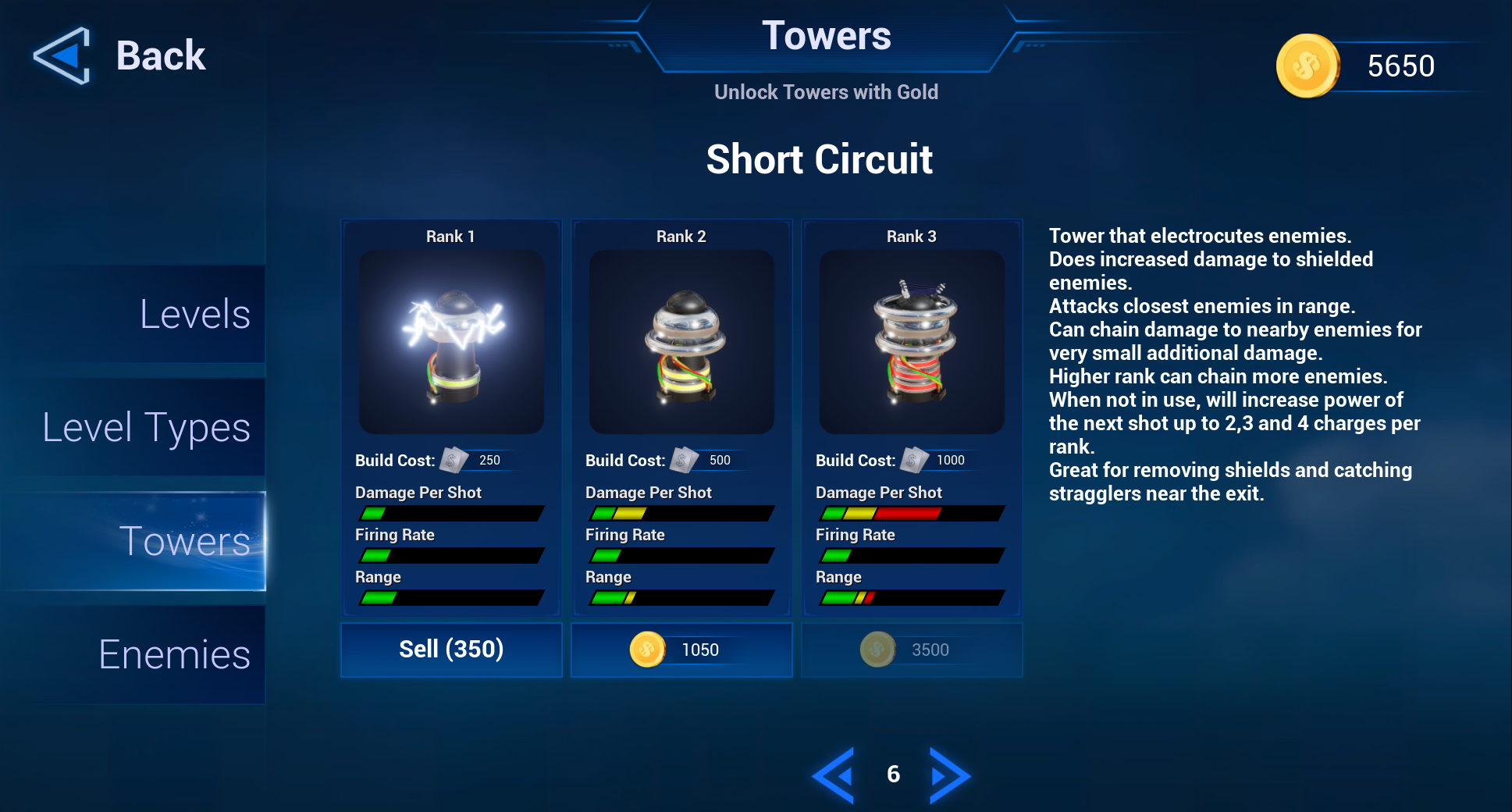
Animations on Tower Unlock screen. This is a still image but the lightning is animated. Most towers will show them shooting. You’ll also be able to see the interval between shots right in the preview.

Of note, you can now sell towers at exactly what you bought it for. So you can change what towers you want to use for different levels. You cannot sell the first two types of towers that are unlocked at the start (gun and sniper).

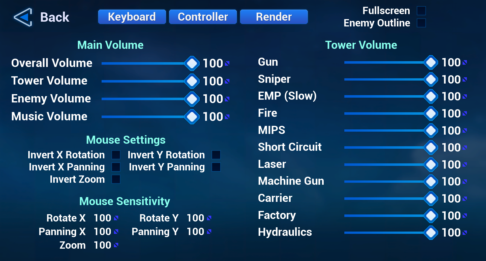
The settings screen is quite busy. A tower defense game can get quite noisy and some towers can be louder than others. I decided to let the user change the volume for each tower individually including the hydraulics sounds when raising and lowering a tower.

Everything is done except the Render Quality screen. Not sure I need it. The game isn’t very taxing on the GPU. At least not right now. But everything on that settings screen is working along with keyboard and controller bindings.

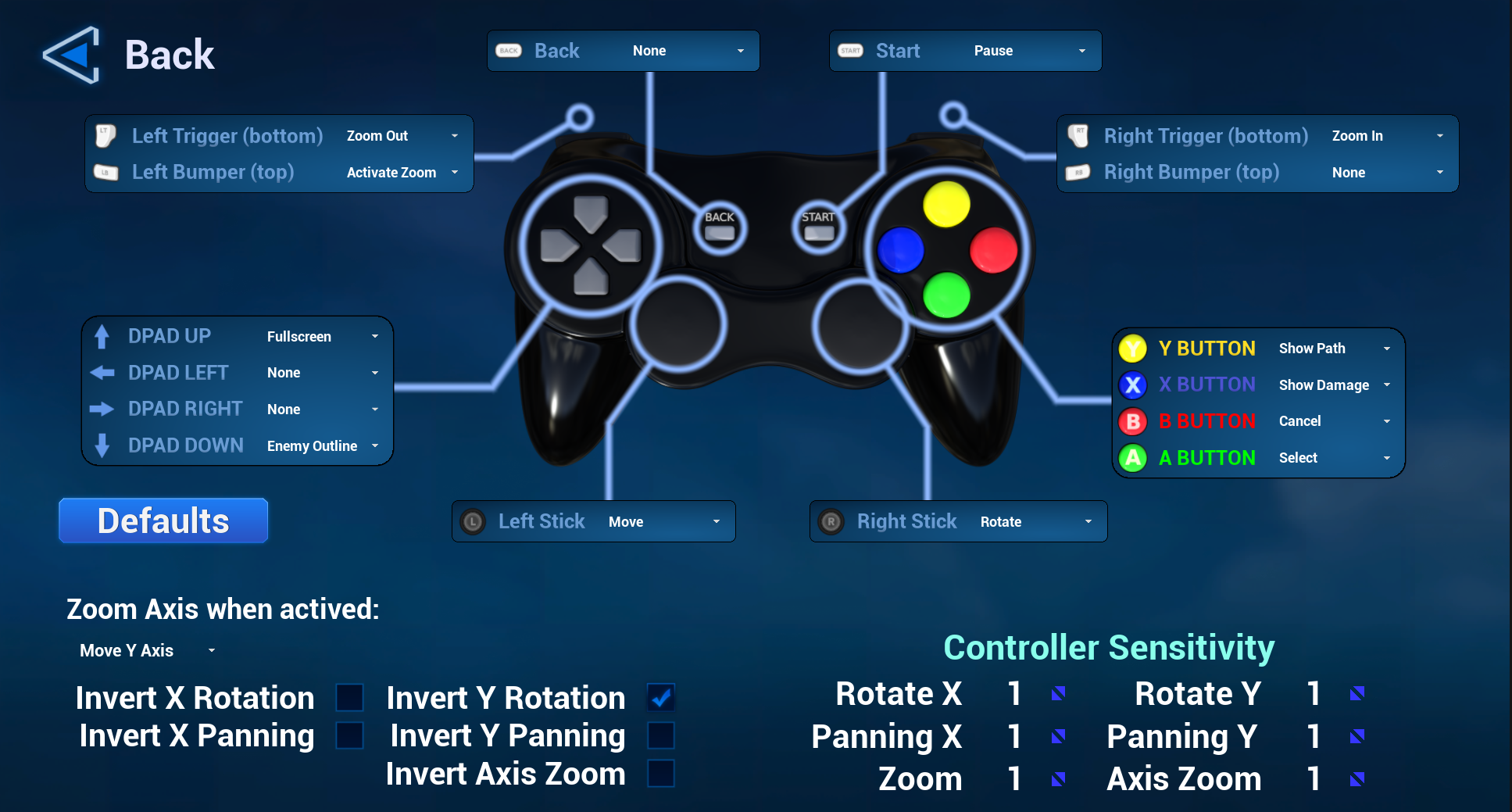
Speaking of which, here is the controller bindings screen. I still have to hid those blue lines until you mouse over them or select them with the controller. But it works as is. And I’m still not sure it’s necessary to hide the lines. I’m thinking of changing the icon for the face buttons depending on what kind of controller you’re using. Again, not sure that’s strictly necessary.

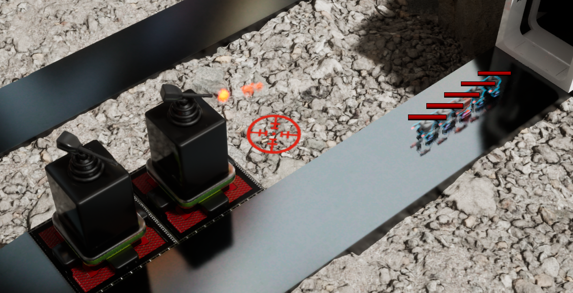
One thing that the reader may have noticed on the main settings screen is that there are settings for showing enemy outlines. I couldn’t find a good colour scheme to create more contrast between the enemies and the roads. So I added an outline option using the stencil buffer. That could be a blog post on its own. But it’s rather technical. Anyhow, it can be toggled on and off in game.

This is a little blurry because they are in motion, but should give a good idea what it looks like.

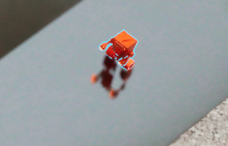
Here it is a little clearer on a death animation.

I’ve also added little idle animations on the towers with a gun (Gun, Sniper and Machine Gun). So the gun rotates around at regular intervals as if it’s scanning for enemies. It’s not actually doing anything. Also, it only does this after a little while. So it shouldn’t interfere with shooting at enemies that all appear in the same direction.

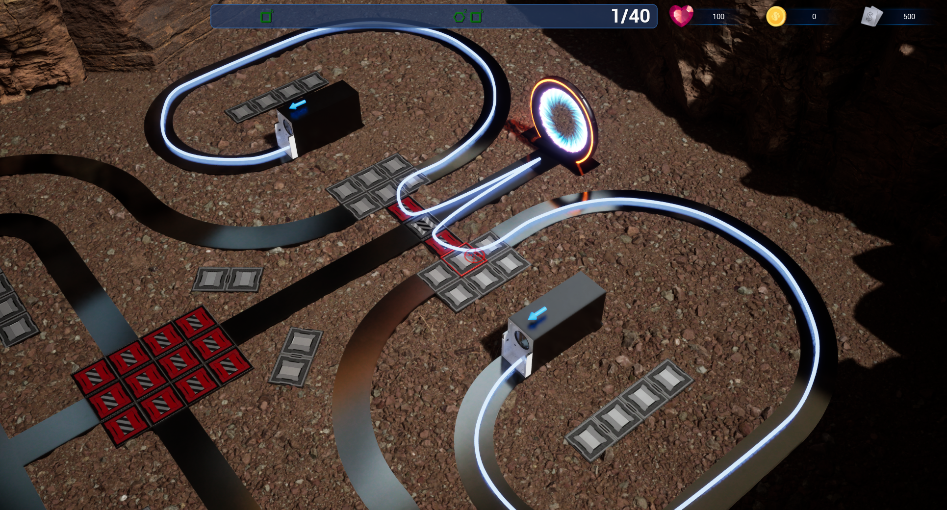
Oh, I’ve added a path preview so you know what path the enemies will take. This can be toggled on and off. In the screenshot below, it’s fairly clear the player needs to block the path to make the enemies take a longer route.

I have a few more towers to make preview animations, finish one settings screen and clean up a couple levels (adds some lights and maybe some other decorations) and I think I’m close to having a demo. I’m really happy with the progress. A lot of the things I’ve added recently aren’t strictly necessary to the game itself. But I find it just adds an extra level of completeness and attention to detail.

Tower Defense update. Blocked Enemies

I think I once said I had no technical challenges left. That’s not 100% accurate. While there’s nothing I have to look up in the engine on how to do, there are still a few technical design decisions left that I’ve been avoiding since I started. Here are those three technical decisions.

  1. What happens if you build towers and the enemies can no longer reach the exit?
  2. What to do when you try to build a tower and enemies appear where you want to build? Note that the game does not pause while you build.
  3. What to do when an enemy reaches the exit.

The third one is a critical part of the game and I’m still trying out different things. The second one could be handled with a delay and disable building more towers until enemies move away.

The first one is the one that I really didn’t want to tackle. At first, I tried to build an internal map, but that got complicated real fast. Then I realized a few thing. First is that you can only build towers on one kind of Actor. These are called PathActors in my game. You can disable building towers on them and still use them in the level for the enemies to use. These are 8×8 tilesets. You can reduce their size with a simple size property. And you just place them side by side. All tiles in my game are 100cm (or 1m). So it’s easy to build an internal graph for this part and connecting them together is just checking what tiles are about 100cm apart. Easy.

Next are the irregular shapes. There are custom shapes and single tile components that can be grouped together into a single actor. I tried a few different things again it just got complicated. Then I had my second realization. Since you cannot build here, only the jointing tiles need to be specified. So I manually added a spline component to these with an endpoint at each end of the path. You can even add more splines if you’d like as long as spline points overlap as connecting points. Again, easy. I just scan for these splines and join them up. It’s a bit of manual work to add the splines, but it just makes thing so much easier.

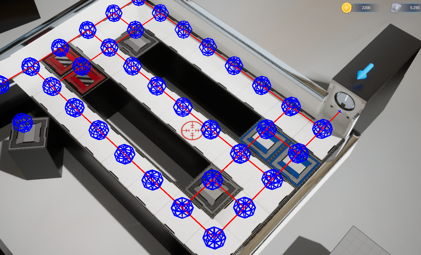
I had a few issues still and drew the internal map. Here is an example (after I fixed my issues).

What is the point of this map? How is it used? I hooked this up to an AStar navmesh. When you want to build a tower, I set a node as blocked (the blue spheres) in the graph and check if the enemies can go from each entrance to their exit. If not, then you can’t build there. In fact, the menu and the selection square won’t even show up.

This took three days to implement. And this was quick because I had to generate the map from the actors in the level. I didn’t want to generate the maps manually. I also reused the AStar code from my first game.

I also learned a few things about navigation meshes. First, you don’t need to spawn one yourself. Instead, you go into the project settings under Engine/Navigation System. Then go to the Agents section and add an agent for your navigation mesh. You can select your navigation mesh class there. Do not remove the main mesh. That’s the one you will use inside your game.

One important thing is that registering a navmesh IS the same as adding it to the list of supported agents. So don’t register your navmesh. It’s not necessary.

To do an internal query, it’s rather simple. You grab the navigation system and do your query there. Like this:

FPathFindingQuery Query;
Query.StartLocation = StartTile->Position;
Query.EndLocation = EndTile->Position;
Query.bAllowPartialPaths = false;
FSharedNavQueryFilter QueryFilter = MakeShareable(new FNavigationQueryFilter());
Query.QueryFilter = QueryFilter;

UNavigationSystemV1* NavSys = FNavigationSystem::GetCurrent<UNavigationSystemV1>(GetWorld());
check(NavSys);
FNavDataConfig config = NavSys->GetSupportedAgents()[2];

FPathFindingResult Result = NavSys->FindPathSync(config, Query);

if (!Result.IsSuccessful() || Result.IsPartial())
  return false;

Note that this is when you don’t use a path following component or a in-level navmesh and just want to do a simple path query.

You select the navmesh you want to use with NavSys->GetSupportedAgents()[n] where n is the index of the agents listed in your project settings. Mine was the third navmesh. The first is the one used in-game by the enemies. The second is used by the UFO’s for the carrier tower. And the third is to verify that you can place a tower.

That’s one issue resolved and it works great. I added some flags that are cached so I don’t need to recheck the same tiles repeatedly. When you build or remove a tower, those flags are erased.

Next I have to finally decide what happens when an enemy reaches the exit and start putting some levels together.

Converting Blueprint to C++ in Unreal Engine

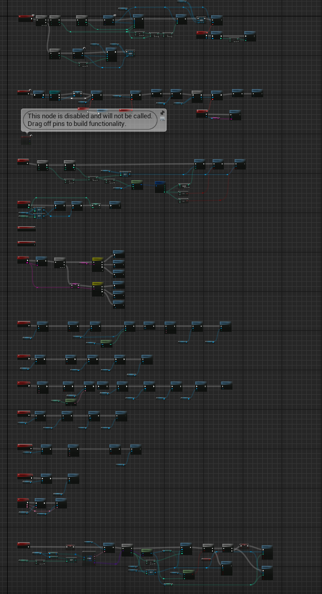
There may come a time when your blueprints just get way too confusing or too large to maintain. In my current game, I tend to use blueprints for UI because this is where there are a lot of binding events on buttons clicks, hovers, etc. So it’s just easier in a blueprint. But after a while, it could turn out like this. Here is a real screenshot from my game. Click on the image to see a larger version.

Note that this is a very technical discussion. If you just want an update on the game, I’m working on the UI and you can just scroll down and look at the screenshots 🙂 They’re still work in progress.

And the worst part is I’m not even done. Luckily, it’s not too difficult to convert this to C++. For this, we need to understand a few things.

First is how inheritance works. All Blueprints are derived from C++ classes. In recent versions of Unreal Engine, you can have blueprints derive from other blueprints with the use of slots, but that’s another discussion. For our purposes, we just need to add our own base class to our widget blueprints. But which blueprints do we add a C++ base class? It will likely be a lot of them. This can create a lot of C++ files. However, there’s a way around this as well that we’ll get into. To start, take the highest level blueprint that is becoming too large and add a C++ base class.

To do this, select the Tools menu and click “New C++ Class”. Then choose the exact same base class as your widget. It will usually be UserWidget, but could also be CommonActivatableWidget if you use CommonUI. Click Next. Type in a name for your class and click “Create Class”. Unreal Engine will try to build this new class using live coding. This will likely crash the editor, so make sure to save before doing any of this. You just need to recompile and relaunch the editor.

Now open up your widget and select the File menu and click on “Reparent Blueprint”. Select the C++ class you just created. Voila. You just added a C++ base class.

The nice part is that everything in C++ can be made accessible to your blueprint by adding “BlueprintReadWrite” (and “EditAnywhere”) to any UPROPERTY or “BlueprintCallable” to any UFUNCTION. If you’re not familiar with how to create properties and UE callable functions, then you’ll need to look that up.

So now you need to start moving variables to your C++ file. For basic types, this is simply adding a UPROPERTY for each variable. I tend to rename all my blueprint variables before doing this. So if I have a variable called “NumTabs”, I’ll rename it to “NumTabX” or “NumTabOld”. The reason for this is that it’s easier to avoid conflicts when you relaunch the editor. It’s a bit more work to refactor, but it’s worth it.

Now close the editor and rebuild. One thing you’ll note is that the C++ properties do not show up in the Variables panel. This is somewhat annoying, but you can still grab the property by right clicking in the blueprint and typing “Get NumTabs” for example and the property will show up. You just can’t drag it in anymore.

To replace the old value, right click on it in the variables panel and click “Find References”. In the new dialog, there is a binocular icon to the right. Click on it. This will search all your blueprints. Now you must replace all the references with your new C++ variable. It’s a bit tedious, but it’s cleaner and you avoid a lot of headaches down the road. Do this for each variable you converted to C++. When done, you can delete the Blueprint version of the variable. It will tell you if there are still references to it.

Replacing variables is ok, but there’s not much point if you can’t use them anywhere. These variable are used with other widgets. So now we are going to replace widget variables. Note that CREATING the widget (for those created at runtime) must remain in the blueprint unless you set the CLASS as a default variable in C++ that you can use to create the widget. This is because you cannot create the C++ class version of the widget as that’s the base class, not the full class. The full class is the Blueprint itself.

So how do we get access to blueprint widget references in C++ if we don’t create them? Well, there’s a way to bind widgets to properties so that you can use them in C++. You’ll only have access to methods defined in C++, but that’s usually good enough. If you need more access (for example if you created custom widgets), you can use the same technique here and/or add C++ methods that can be implemented in blueprints. We’ll get into that later.


For binding widgets as properties, we do NOT change the names. The editor will automatically update everything. So all you have to do is add this property to your C++ header.

UPROPERTY(EditAnywhere, BlueprintReadWrite, meta = (BindWidget))
TObjectPtr<UTextBlock> TextBlock_Points;


That’s an example of a TextBlock widget binding. One thing to note is that the property name must match EXACTLY what it is named in the Blueprint. Other widgets tend to have the same name with U added in front like UImage.

For any pre-existing widget, it’s that easy.

Now you can start converting your events to C++ functions (UFUNCTION) that are callable from blueprints.


To bind custom widgets, you will have to either bind to UserWidget class (where you will not be able to call custom events you added from C++) or add a custom base C++ class as done previously. Then you can bind to that class and move your events there so that Class 1 can call functions in Class 2.

If this starts to chain out of control, there is a way out.

Instead of converting every event, you can instead just declare a function that can be implemented in a blueprint. So this allows you to call blueprint code from C++.


In my game, there is a place where I want to show the Pause menu from C++ code. But the pause menu is completely implemented in blueprint. How did I do call this from C++?

UFUNCTION(BlueprintImplementableEvent, Category = “UI”)
void ShowPauseMenu();

By adding the above function in my C++ header, I then implemented it in the blueprint that has this class as its base class. You can override it in the blueprint by using the little dropdown in the FUNCTIONS header panel.


This is a way to avoid converting everything. This is useful in smaller custom widgets. You still need to add a custom base C++ class, but you don’t need to move all the variable or code down to it. You just add the functions you want access to and the base C++ class allows you to bind to it in other higher level widgets that’s you’ve added a C++ base class.


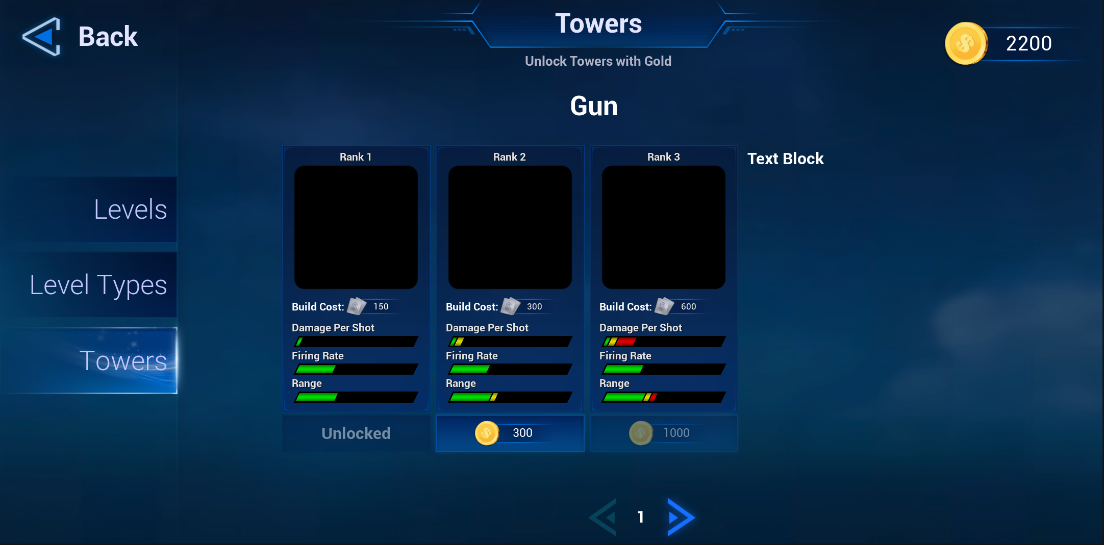
Here are a few examples of converting blueprint to C++. I have a screen for unlocking towers. It’s not complete yet. Still need to update the preview image and add longer description for example, but here’s a screenshot.

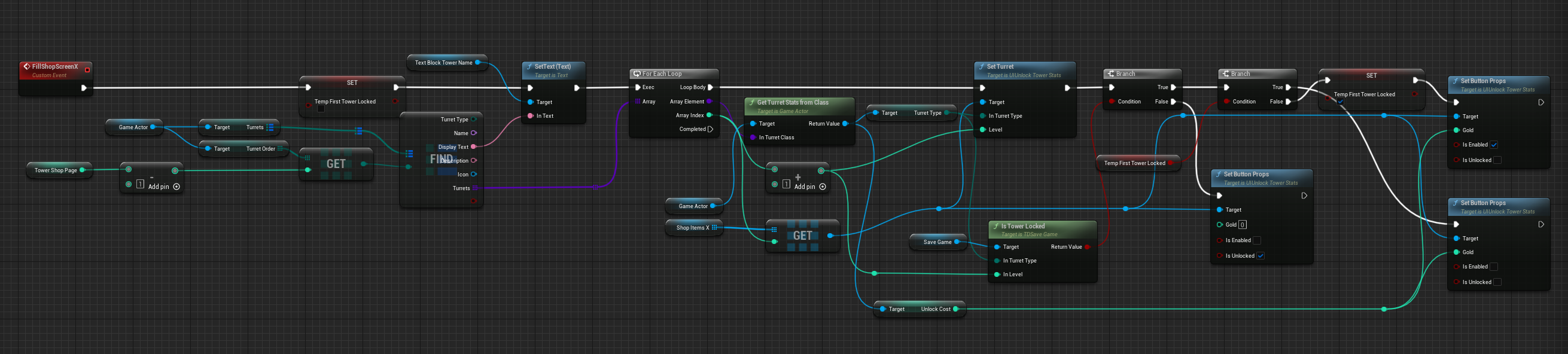
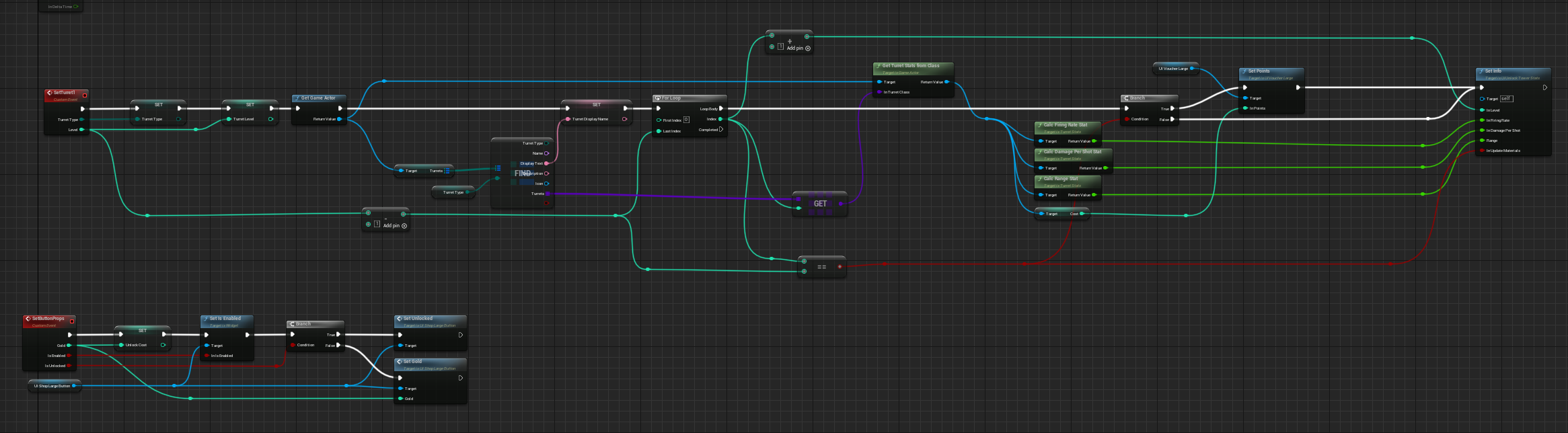
Here’s the blueprint graph just to fill in the data for each tower.

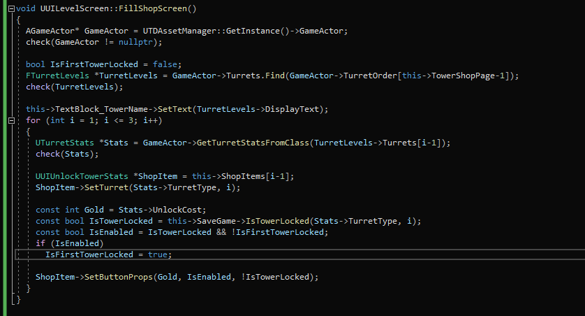
Just one graph like that isn’t too bad, but this is the bottom graph of the first image at the top. So it was getting way too complicated. After converting this to C++, here’s my code:

It is a 1 to 1 conversion. I find the C++ code much easier to read and maintain.

In the TurretStats widget, I had an event called SetTurret that sets up all the stats bars, cost, title, etc. You can see this function called in both the blueprint and C++ code above. Here is the blueprint version (the top graph).

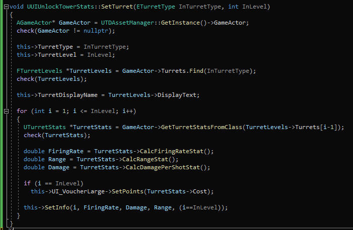
Here is the C++ version.

In the C++ code, it’s easier to see what’s going on. It’s just grabbing 3 stats and setting it on the current widget. It’s setting also setting the display name. The reason there’s a loop is so you can compare the new stats with the previous level’s stats. The stats are displayed overlapping each other as seen in the blue unlock screenshot above (in green, yellow and red bars).

I didn’t go into delegates or event bindings. Those are a bit more complicated. I tend to leave those in the blueprints though I have used them in C++. I had once tried to create a UE interface in C++ and make blueprints implement those methods so that I could call those methods from C++ instead of having to create C++ base classes for each widget. Well, there’s a little undocumented snag with that. You can’t call UE interfaces from C++ unless that interface is directly implemented in C++ as well. It will literally do nothing if you call a UE interface defined in C++ that is implemented in a Blueprint. Now, there is a way to call it. You need a pointer to the widget and you call Execute_MyFunction(MyWidget) instead of just calling MyFunction. Also, the references to the interfaces are whack when dealing with blueprints, especially if you’re passing them around. They’re not just pointers. Short story is that UE interfaces were not worth the pain.


What we have here is one scenario where converting to C++ is not done for speed at all. In fact, I’d be more than happy to keep everything as blueprints. But sometimes it’s just easier to write small snippets of C++ code. Blueprint is great for prototyping and if it doesn’t need much more work, leave it as a blueprint. But for things that need a little more setup, I find it’s just easier to code in C++. And yes, you can use the exact same techniques with actors and regular blueprints.

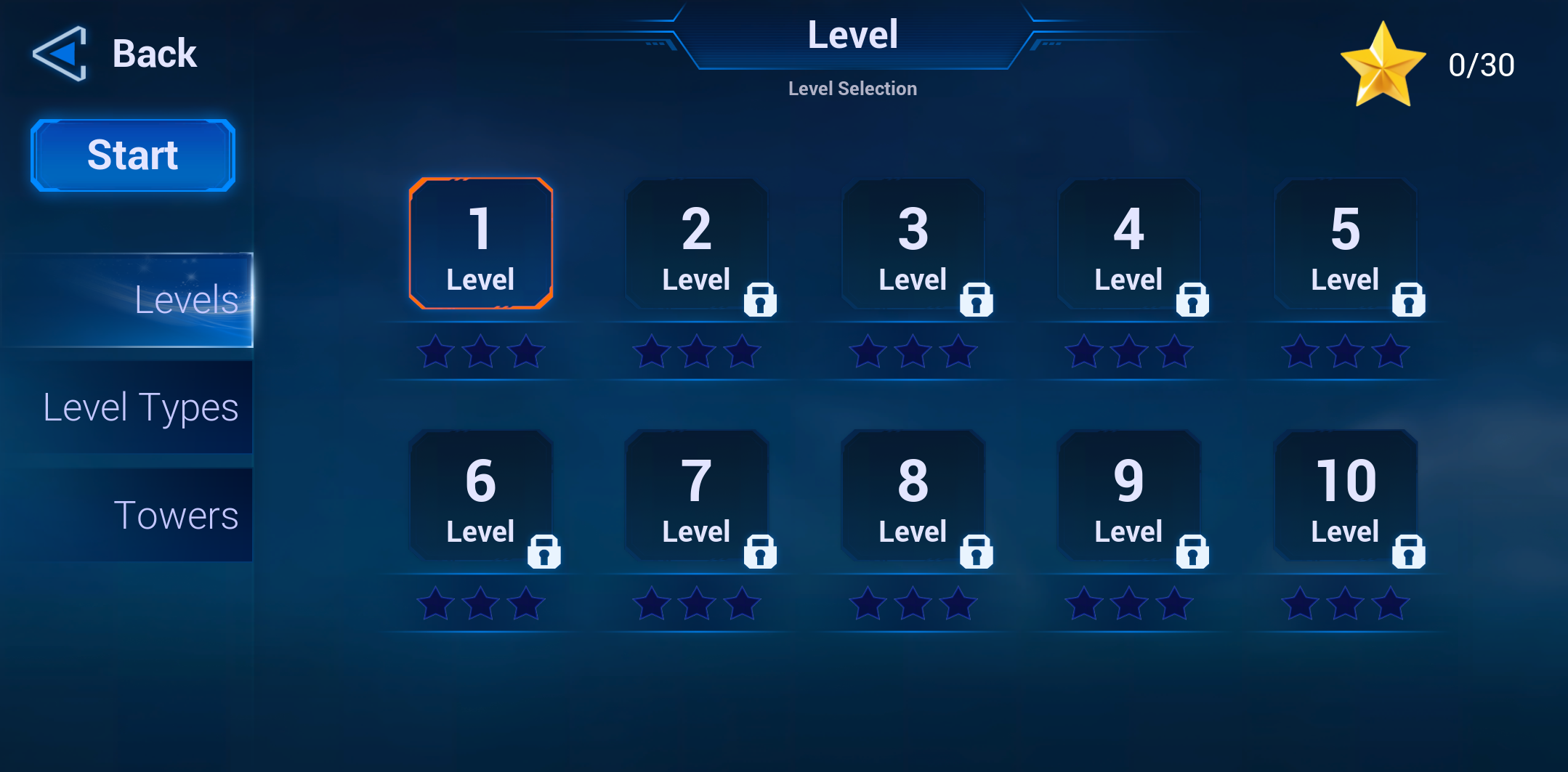
Finally, my levels screen.

Once I’m done the tower unlock screen, I need to do a bit more work on the gameplay. I finally need to resolve what happens when a robot reached the end and what happens if you block off the path to the exit. Those are the last real issues left. I’ve written down a few ideas for more levels. So if I can make one or two half decent levels, I’ll likely make a demo. I’m starting to create my store page on steam and looking into making a game page. Stay tuned for that!